
DirectX 12 – Lesson 2
This is the second lesson in a series of lessons to teach you how to create a DirectX 12 powered application from scratch. In this lesson, vertex and index data is uploaded to the Graphics Processing Unit (GPU) for rendering. Basic vertex and pixel shaders are described and how to create a Pipeline State Object (PSO) that utilizes those shaders is also described. A root signature defines the parameters that are used by the stages of the rendering pipeline. In this lesson a simple root signature is created that defines a single constant buffer that contains the Model-View-Projection (MVP) matrix that is used to rotate a model in the scene.
Introduction
In the previous lesson you learned how to initialize a DirectX 12 application. You also learned how to synchronize the CPU and GPU operations in order to correctly implement N-buffered rendering. At the end of the previous lesson, you had a DirectX 12 application that performed a screen clear but nothing was rendered to the screen. In this lesson, you learn how to render a simple cube primitive. Texturing and lighting is the subject of a later lesson. This lesson assumes you have read and understand the concepts presented in the previous lesson. If not, please take the time to read the first lesson before reading this one.
It is important to understand a few new concepts when working with DirectX 12. One such concept is resource usage in DirectX 12. In previous versions of the DirectX API, there were different interfaces depending on the resource type. For example, a buffer and a texture (1D, 2D, and 3D) each had an interface to describe the resource type. In DirectX 12 the only interface used to describe a resource is the ID3D12Resource interface.
DirectX 12 also provides more control over the way the resource is stored in GPU memory. The ID3D12Heap interface allows for various memory mapping techniques to be implemented which may be used to optimize GPU memory utilization.
In order to provide better state management in DirectX 12, the pipeline state object (PSO) is used to describe the various stages of the rendering (and compute) pipeline. The PSO combines parts of the input assembly (IA), vertex shader (VS), hull shader (HS), domain shader (DS), geometry shader (GS), stream output (SO), rasterizer stage (RS), pixel shader (PS), and output merger (OM) stages of the rendering pipeline. A few properties of the rendering pipeline (such as viewport and scissor rectangle) require additional API calls but most of the configuration of the rendering pipeline is controlled by the PSO.
Another new concept in DirectX 12 is the root signature. A root signature describes the parameters that are passed to the various programmable shader stages of the rendering pipeline. Examples of parameters that are passed to the programmable shader stages are constant buffers, (read-write) textures, and (read-write) buffers. Texture samplers (an object that determines how the texels in a texture are sampled and filtered) are also defined in the root signature. In this lesson, a very simple root signature is created that uses a constant buffer parameter to rotate a cube in the scene. More complex uses of the root signature will be described in a later lesson.
At the end of this lesson you should have a better understanding of the following concepts:
- Uploading Buffer Resources to the GPU
- Heaps
- Pipeline State Objects
- Root signatures
Heaps and Resources
In the first lesson a swap chain is created which internally contains one or more texture resources that are used to present the final rendered image to the screen. The creation of the texture resource for the swap chain is hidden in the IDXGIFactory2::CreateSwapChainForHwnd method. In this case, the graphics programmer has no control over how and where the resource is created. In this lesson, several buffer resources are required to render the scene. For these resources, the graphics programmer must decide how those buffer resources are created. There are several different ways that GPU resources are allocated within a memory heap (ID3D12Heap):
- Committed Resources
- Placed Resources
- Reserved Resources
In the next section, the various resource allocation methods are described.
Committed Resources
A committed resource is created using the ID3D12Device::CreateCommittedResource method. This method creates both the resource and an implicit heap that is large enough to hold the resource. The resource is also mapped to the heap. Committed resources are easy to manage because the graphics programmer doesn’t need to be concerned with placing the resource within the heap.
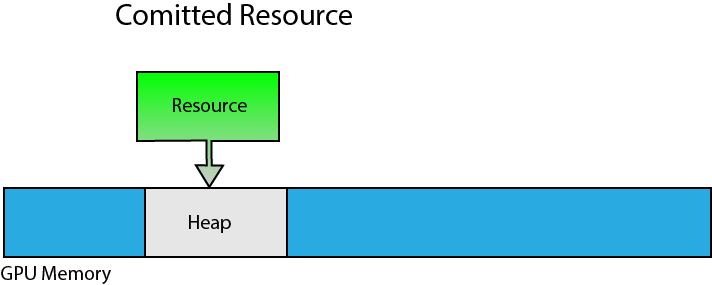
Committed resources are created in an implicit heap.
Committed resources are ideal for allocating large resources like textures or statically sized resources (the size of the resource does not change). Committed resource are also commonly used to create large resource in an upload heap that can be used for uploading dynamic vertex or index buffers (useful for UI rendering or uploading constant buffer data that is changing for each draw call).
Placed Resources
A placed resource is explicitly placed in a heap at a specific offset within the heap. Before a placed resource can be created, first a heap is created using the ID3D12Device::CreateHeap method. The placed resource is then created inside the heap using the ID3D12Device::CreatePlacedResource method.
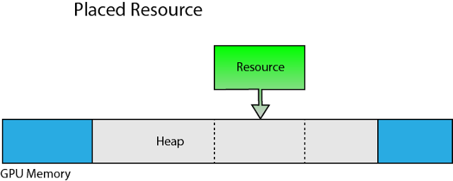
Placed resources are placed at a specific offset within a specific memory heap.
Although placed resource provide better performance because the heap does not need to be allocated from global GPU memory for each resource, using placed resources correctly does require some discipline from the graphics programmer. Placed resources provides more options for implementing various memory management techniques but with great power comes great responsibility. When using placed resources, there are some limitations that must be taken into consideration.
The size of the heap that will be used for placed resources must be known in advance. Creating larger than necessary heaps is not a good idea because the only way to reclaim the GPU memory used by the heap is to either evict the heap or completely destroy it. Since you can only evict an entire heap from GPU memory, any resources that are currently placed in the heap must not be referenced in a command list that is being executed on the GPU.
Depending on the GPU architecture, the type of resource that you can allocate within a particular heap may be limited. For example, buffer resources (vertex buffer, index buffer, constant buffer, structure buffer, etc..) can only be placed in a heap that was created with the ALLOW_ONLY_BUFFERS heap flag. Render target and depth/stencil resources can only be placed in a heap that was created with the ALLOW_ONLY_RT_DS_TEXTURES heap flag. Non render target textures can only be placed in a heap that was created with the ALLOW_ONLY_NON_RT_DS_TEXTURES heap flag. Adapters that support heap tier 2 and higher can create heaps using the ALLOW_ALL_BUFFERS_AND_TEXTURES heap flag to allow any resource type to be placed within that heap. Since the heap tier is dependent on the GPU architecture, most applications will probably be written assuming only heap tier 1 support.
Multiple placed resources can be aliased in a heap as long as they don’t access the same aliased heap space at the same time.
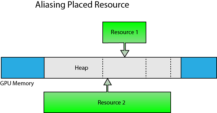
Placed resources can be aliased within the heap.
Aliasing can help to reduce oversubscribing GPU memory usage since the size of the heap can be limited to the size of the largest resource that will be placed in the heap at any moment in time. Aliasing can be used as long as the same space in the heap is not used by multiple aliasing resources at the same time. Aliased resources can be swapped using a resource aliasing barrier.
Reserved Resources
Reserved resources are created without specifying a heap to place the resource in. Reserved resources are created using the ID3D12Device::CreateReservedResource method. Before a reserved resource can be used, it must be mapped to a heap using the ID3D12CommandQueue::UpdateTileMappings method.
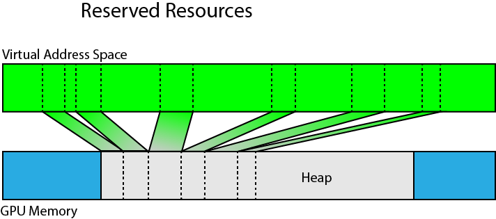
Portions of a reserved resource can be mapped to a heap in physical GPU memory.
Reserved resources can be created that are larger than can fit in a single heap. Portions of the reserved resource can be mapped (and unmapped) using one or more heaps residing in physical GPU memory.
Using reserved resources, a large volume texture can be created using virtual memory but only the resident spaces of the volume texture needs to be mapped to physical memory. This resource type provides options for implementing rendering techniques that use sparse voxel octrees [2] without exceeding GPU memory budgets.
Pipeline State Object
The various stages of the rendering pipeline were briefly described in the first lesson. Please refer to that lesson if you are not familiar with the stages of the rendering pipeline.
The Pipeline State Object (PSO) contains most of the state that is required to configure the rendering (or compute) pipeline. The graphics pipeline state object includes the following information [3]:
- Shader bytecode (vertex, pixel, domain, hull, and geometry shaders)
- Vertex format input layout
- Primitive topology type (point, line, triangle, or patch)
- Blend state
- Rasterizer state
- Depth-stencil state
- Number of render targets and render target formats
- Depth-stencil format
- Multisample description
- Stream output buffer description
- Root signature
The pipeline state object structure contains a lot of information and if any of the state needs to change between draw calls (for example, a different pixel shader or blend state is needed) then a new pipeline state object needs to be created.
Although the pipeline state object contains a lot of information, there are a few additional parameters that must be set outside of the pipeline state object.
- Vertex and Index buffers
- Stream output buffer
- Render targets
- Descriptor heaps
- Shader parameters (constant buffers, read-write buffers, and read-write textures)
- Viewports
- Scissor rectangles
- Constant blend factor
- Stencil reference value
- Primitive topology and adjacency information
The pipeline state object can optionally be specified for a graphics command list when the command list is reset using the ID3D12GraphicsCommandList::Reset method but it can also be changed for the command list at any time using the ID3D12GraphicsCommandList::SetPipelineState method.
Root Signatures
A root signature is similar to a C++ function signature, that is, it defines the parameters that are passed to the shader pipeline. The values that are bound to the pipeline are called the root arguments. The arguments that are passed to the shader can change without changing the root signature parameters.
The root parameters in the root signature not only define the type of the parameters that are expected in the shader, they also define the shader registers and register spaces to bind the arguments to in the shader.
Shader Register & Register Spaces
Shader parameters must be bound to a register. For example, constant buffers are bound to b registers (b0 – bN), shader resource views (textures and non-constant buffer types) are bound to t registers (t0 – tN), unordered access views (writeable textures and buffer types) are bound to u registers (u0 – uN), and texture samplers are bound to s registers (s0 – sN) where N is the maximum number of shader registers.
In previous versions of DirectX, different resources could be bound to the same register slot if they were used in different shader stages of the rendering pipeline. For example, a constant buffer could be bound to register b0 in the vertex shader and a different constant buffer could be bound to register b0 in the pixel shader without causing overlap.
DirectX 12 root signatures require that all shader parameters be defined for all stages of the rendering pipeline and registers used across different shader stages may not overlap. In order to provide a work-around for legacy shaders that may violate this rule, Shader Model 5.1 introduces register spaces. Resources can overlap register slots as long as they don’t also overlap register spaces.
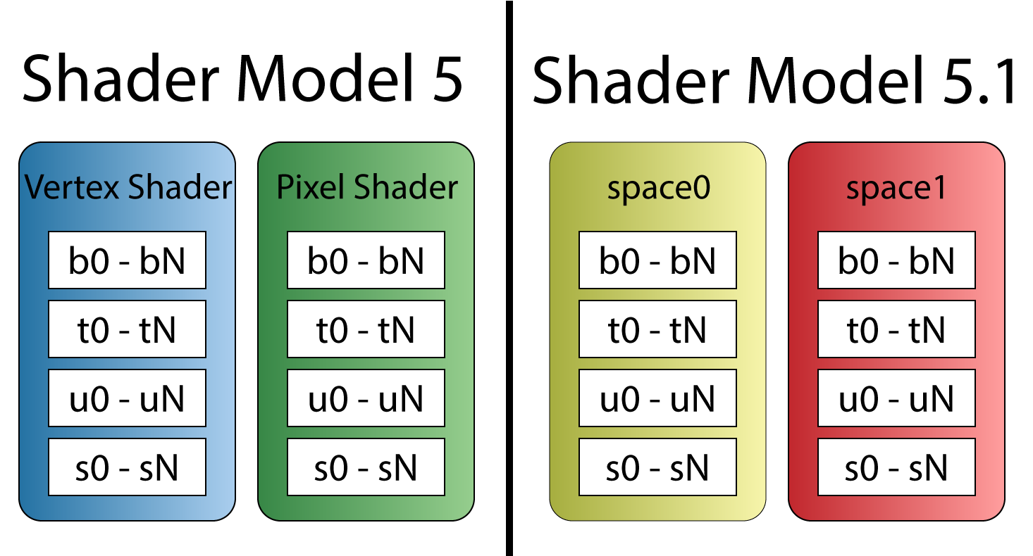
Prior to Shader Model 5.1, resource registers could overlap across shader stages (left). Shader Model 5.1 introduces shader spaces which can be used to overlap register slots (right).
It is important for the graphics programmer to understand the shader register and register spaces overlapping rules when porting legacy shaders to DirectX 12.
Root Signature Parameters
A root signature can contain any number of parameters. Each parameter can be one of the following types:
D3D12_ROOT_PARAMETER_TYPE_32BIT_CONSTANTS: 32-bit Root ConstantsD3D12_ROOT_PARAMETER_TYPE_CBV: Inline CBV DescriptorD3D12_ROOT_PARAMETER_TYPE_SRV: Inline SRV DescriptorD3D12_ROOT_PARAMETER_TYPE_UAV: Inline UAV DescriptorD3D12_ROOT_PARAMETER_TYPE_DESCRIPTOR_TABLE: Descriptor Table
32-Bit Constants
Constant buffer data can be passed to the shader without the need to create a constant buffer resource by using the 32-bit constants. Dynamic indexing into the constant buffer data is not supported for constant data that is stored in the root signature space [4]. For example, the following constant buffer definition can be mapped to 32-bit constants stored in the root signature:
|
1 2 3 4 5 6 |
cbuffer TransformsCB : register(b0, space0) { matrix Model; matrix View; matrix Projection; } |
But, due to the array, the following constant buffer definition cannot be mapped to 32-bit constants in the root signature and instead requires either an inline descriptor or a descriptor heap to map the resource:
|
1 2 3 4 |
cbuffer TransformsCB : register(b0, space0) { matrix MVPMatrices[3]; } |
Each root constant in the root signature costs 1 DWORD (32-bits) [5].
Inline Descriptors
Descriptors can be placed directly in the root signature without requiring a descriptor heap [6]. Only constant buffers (CBV), and buffer resources (SRV, UAV) resources containing 32-bit (FLOAT, UINT, or SINT) components can be accessed using inline descriptors in the root signature. Inline UAV descriptors for buffer resources cannot contain counters (for example, if a RWStructuredBuffers contains a counter resource, it may not be accessed through an inline descriptor in the root signature. Texture resources cannot be referenced using inline descriptors in the root signature and must be placed in a descriptor heap and referenced through a descriptor table.
Unlike root constants, constant buffers containing arrays may be accessed using inline descriptors in the root signature. For example, the following constant buffer can be referenced using inline descriptors:
|
1 2 3 4 5 6 |
cbuffer SceneData : register(b0, space0) { uint foo; float bar[2]; int moo; }; |
Each inline descriptor in the root signature costs 2 DWORDs (64-bits) [5].
Descriptor Tables
A descriptor table defines several descriptor ranges that are placed consecutively in a GPU visible descriptor heap.
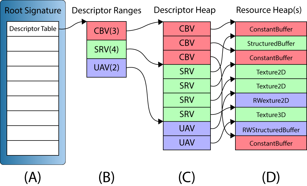
A descriptor table (A) in a root signature defines a set of one or more descriptor ranges (B). The descriptor ranges define a set of consecutive descriptors in a GPU visible descriptor heap (C). The descriptors are views to the GPU resources stored in one or more resource heaps (D).
The above image illustrates a root signature with a single descriptor table parameter (A). The descriptor table contains three descriptor ranges (B): 3 Constant Buffer Views (CBV), 4 Shader Resource Views (SRV), and 2 Unordered Access Views (UAV). CBV’s, SRV’s and UAV’s can be referenced in the same descriptor table since all three types of descriptors can be stored in the same descriptor heap. The GPU visible descriptors (C) must appear consecutively in a GPU visible descriptor heap but the resources that they refer to (D) may appear anywhere in GPU memory, even in different resource heaps.
The above image shows a simplified version of the descriptor table ranges. The descriptor ranges in a descriptor table also need to specify the register slots and spaces that the arguments will be bound to in the shaders. An example of configuring a root signature will be shown later in the lesson.
Each descriptor table in the root signature costs 1 DWORD (32-bits) [5].
Static Samplers
A texture sampler describes how a texture should be sampled. It describes the filtering, addressing, and Level of Detail (LOD) to use while sampling from a texture. Using textures and texture samplers will be the topic of another lesson. In this lesson, it is important to understand that texture samplers can be defined directly in the root signature without the need of a descriptor heap. The D3D12_STATIC_SAMPLER_DESC structure is used to define a texture sampler directly in the root signature.
Static samplers do not use any space in the root signature and do not count against the size limit of the root signature.
Root Signature Constraints
Root signatures are limited to 64 DWORDs (2048-bits) [5]. Each root parameter has a cost that counts towards the root signature limit:
- 32-bit constants each costs 1 DWORD
- Inline descriptors each costs 2 DWORDs
- Descriptor tables each costs 1 DWORD
Static samplers defined in the root signature do not count towards the size of the root signature.
The cost of accessing a root argument in a root signature in terms of levels of indirection is zero for 32-bit constants, 1 for inline descriptors, and 2 for descriptor tables [5].
The graphics programmer should strive to achieve a root signature that is as small as possible but balance the flexibility of using a larger root signature. Parameters in the root signature should be ordered based on the likelihood that the arguments will change. If the root arguments are changing often then they should appear first in the root signature. If the root arguments are not changing often, then they should be the last parameters that appear in the root signature. Since 32-bit constants and inline descriptors have better performance in terms of level of indirection, they should be favored over using descriptor tables as long as the size of the root signature does not become to large.
An example of a simple root signature is provided later in this lesson.
DirectX 12 Demo
The previous lesson showed how to initialize a DirectX 12 application without using any C++ classes. Some of the source code from the first lesson was refactored in order to simplify the source code for this and future lessons. There are three primary classes that are used for this lesson:
ApplicationWindowCommandQueueGame
The Application class is responsible for initializing application specific data such as the DirectX 12 device and command queues. The Application class is also responsible for creating the Window instances and it is also the owner of the Window instances (Window instances can only be created and destroyed using the Application class). The Application class also exposes a Run method which is used to run the game and execute the message loop. The Quit method is used to quit the running application.
The Window class creates the swap chain which contains the final rendered image that will be presented to the screen. The Window class also contains functions to resize the window and toggle vsync, and fullscreen state.
The source code for the Application and the Window classes are not discussed in this lesson. You are encouraged to go back to the previous lesson if you are not familiar with the functionality of these classes. You may also refer to the source code for this lesson on GitHub. A link to the source code for this lesson also is provided at the end of the tutorial.
The CommandQueue and the Game class on the other hand may not be immediately clear and therefore will be discussed in greater detail in this lesson.
If you would prefer to skip the discussion on refactoring of the CommandQueue and Game classes then you can continue directly to the section about Shaders. Be aware that you may see code later in the lesson that you are not familiar with if you skip these sections.
The Command Queue Class
The CommandQueue class encapsulates the ID3D12CommandQueue interface and the syncronization primitives that are used to perform GPU synchronization with the CPU. Most of the functionality of this class was discussed in the previous lesson so it should already be familiar but it is important to understand the specific choices that were made while creating the class before seeing it used in the demo.
CommandQueue Header
The CommandQueue class must provide the following functionality:
- Get a command list that can be used to record the draw commands
- Execute the command list on the command queue
- Signal a Fence in the command queue
- Check to see if a particular fence value has been reached
- Wait for a particular fence value to be reached
- Flush any pending commands that are executing on the command queue
The class diagram for the CommandQueue class might look like this:
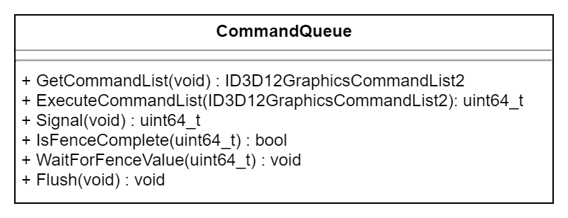
The public interface of the CommandQueue class.
CommandQueue Preamble
The CommandQueue has some dependencies on some system headers which are included first.
|
1 2 3 4 5 6 7 8 9 10 11 |
/** * Wrapper class for a ID3D12CommandQueue. */ #pragma once #include <d3d12.h> // For ID3D12CommandQueue, ID3D12Device2, and ID3D12Fence #include <wrl.h> // For Microsoft::WRL::ComPtr #include <cstdint> // For uint64_t #include <queue> // For std::queue |
The d3d12.h header file is required for the ID3D12CommandQueue, ID3D12Device2, and ID3D12Fence interfaces. The wrl.h header is required for the ComPtr class. The cstdint header is used for the uint64_t integer type and the queue header is used for the std::queue template class.
CommandQueue Class Definition
The public methods of the class are shown first.
|
1 2 3 4 5 6 7 8 9 10 11 12 13 14 15 16 17 18 19 |
class CommandQueue { public: CommandQueue(Microsoft::WRL::ComPtr<ID3D12Device2> device, D3D12_COMMAND_LIST_TYPE type); virtual ~CommandQueue(); // Get an available command list from the command queue. Microsoft::WRL::ComPtr<ID3D12GraphicsCommandList2> GetCommandList(); // Execute a command list. // Returns the fence value to wait for for this command list. uint64_t ExecuteCommandList(Microsoft::WRL::ComPtr<ID3D12GraphicsCommandList2> commandList); uint64_t Signal(); bool IsFenceComplete(uint64_t fenceValue); void WaitForFenceValue(uint64_t fenceValue); void Flush(); Microsoft::WRL::ComPtr<ID3D12CommandQueue> GetD3D12CommandQueue() const; |
The parameterized constructor for the class takes the DirectX 12 device and the type of the command queue to create as arguments. Creation of the DirectX 12 device and the different types of command queues was discussed in the previous lesson.
The GetCommandList method declared on line 20 returns a command list that can be used to issue drawing commands. The command list returned from this method will be in a state that it can immediately be used to issue commands. There is no need to reset the command list or to create a command allocator for the command list.
After the commands have been recorded into the command list, they can be executed on the command queue using the ExecuteCommandList method declared on line 24. The ExecuteCommandList method returns the fence value that can be used to check if the commands in the command list have finished executing on the command queue.
The functionality of the Signal, IsFenceComplete, WaitForFenceValue, and Flush methods declared on lines 26-29 have the same functionality as that described in the previous lesson and will not be discussed any further in this lesson.
The GetD3D12CommandQueue method defined on line 31 is used to get access to the underlying ID3D12CommandQueue interface.
The protected methods are described next.
|
1 2 3 4 |
protected: Microsoft::WRL::ComPtr<ID3D12CommandAllocator> CreateCommandAllocator(); Microsoft::WRL::ComPtr<ID3D12GraphicsCommandList2> CreateCommandList(Microsoft::WRL::ComPtr<ID3D12CommandAllocator> allocator); |
The CreateCommandAllocator and CreateCommandList methods are used to create a command allocator and command list if no command list or command allocator are currently available.
Data that is private to the CommandQueue class is described next.
|
1 2 3 4 5 6 7 8 9 10 11 12 13 14 15 16 17 18 19 20 21 |
private: // Keep track of command allocators that are "in-flight" struct CommandAllocatorEntry { uint64_t fenceValue; Microsoft::WRL::ComPtr<ID3D12CommandAllocator> commandAllocator; }; using CommandAllocatorQueue = std::queue<CommandAllocatorEntry>; using CommandListQueue = std::queue< Microsoft::WRL::ComPtr<ID3D12GraphicsCommandList2> >; D3D12_COMMAND_LIST_TYPE m_CommandListType; Microsoft::WRL::ComPtr<ID3D12Device2> m_d3d12Device; Microsoft::WRL::ComPtr<ID3D12CommandQueue> m_d3d12CommandQueue; Microsoft::WRL::ComPtr<ID3D12Fence> m_d3d12Fence; HANDLE m_FenceEvent; uint64_t m_FenceValue; CommandAllocatorQueue m_CommandAllocatorQueue; CommandListQueue m_CommandListQueue; }; |
The CommandAllocatorEntry structure defined on lines 39-43 is used to associate a fence value with a command allocator. As discussed in the previous lesson, the command list can be reused immediately after it has been executed on the command queue, but the command allocator cannot be reused unless the commands stored in the command allocator have finished executing on the command queue. In order to guarantee that the command allocator is no longer “in-flight” on the command queue, a fence value is signaled on the command queue and that fence value (together with the associated command allocator) is stored for later reuse.
The CommandAllocatorQueue aliased on line 45 describes the std::queue object that is used to queue command allocators that are “in-flight” on the GPU queue. As soon as the fence value that is associated with the CommandAllocatorEntry has been reached, the command allocator can be reused.
Similar to the CommandAllocatorEntry, the CommandListQueue alias describes an std::queue object that is used to queue command lists that can be reused. There is no need to associate a fence value with the command lists since they can be reused right after they have been executed on the command queue.
Since there are several different types of command queues as described in the previous lesson, the command queue (command list) type is stored in the m_CommandListType member variable defined on line 48.
The m_d3d12Device member variable defined on line 49 stores a pointer to the ID3D12Device2 interface that is used to create the command queue, command lists, and command allocators used by this class.
The m_d3d12CommandQueue member variable declared on line 50 is used to store the pointer to the ID3D12CommandQueue interface that is owned by this class.
The m_d3d12Fence, m_FenceEvent, and m_FenceValue member variables are the synchronization primitives required to perform CPU-GPU synchronization. These primitives were discussed in the previous lesson and will not be discussed any further in this lesson.
The m_CommandAllocatorQueue and m_CommandListQueue member variables define the command allocator queue and command list queue that are used to queue up command allocators and command lists that can be reused.
CommandQueue Implementation
In this section, the implementations of the methods defined in the CommandQueue class are shown.
CommandQueue::CommandQueue
The CommandQueue constructor is used to create an instance of the CommandQueue class (obviously).
|
1 2 3 4 5 6 7 8 9 10 11 12 13 14 15 16 17 |
CommandQueue::CommandQueue(Microsoft::WRL::ComPtr<ID3D12Device2> device, D3D12_COMMAND_LIST_TYPE type) : m_FenceValue(0) , m_CommandListType(type) , m_d3d12Device(device) { D3D12_COMMAND_QUEUE_DESC desc = {}; desc.Type = type; desc.Priority = D3D12_COMMAND_QUEUE_PRIORITY_NORMAL; desc.Flags = D3D12_COMMAND_QUEUE_FLAG_NONE; desc.NodeMask = 0; ThrowIfFailed(m_d3d12Device->CreateCommandQueue(&desc, IID_PPV_ARGS(&m_d3d12CommandQueue))); ThrowIfFailed(m_d3d12Device->CreateFence(m_FenceValue, D3D12_FENCE_FLAG_NONE, IID_PPV_ARGS(&m_d3d12Fence))); m_FenceEvent = ::CreateEvent(NULL, FALSE, FALSE, NULL); assert(m_FenceEvent && "Failed to create fence event handle."); } |
On lines 10-14 the D3D12_COMMAND_QUEUE_DESC structure is described and on line 16 the ID3D12CommandQueue is created.
The fence object that is used to perform CPU-GPU synchronization is created on line 17 and the fence event is created on line 19.
CommandQueue::CreateCommandAllocator
The CreateCommandAllocator method is used to create a new instance of a ID3D12CommandAllocator.
|
1 2 3 4 5 6 7 |
Microsoft::WRL::ComPtr<ID3D12CommandAllocator> CommandQueue::CreateCommandAllocator() { Microsoft::WRL::ComPtr<ID3D12CommandAllocator> commandAllocator; ThrowIfFailed(m_d3d12Device->CreateCommandAllocator(m_CommandListType, IID_PPV_ARGS(&commandAllocator))); return commandAllocator; } |
The ID3D12Device::CreateCommandAllocator method is used to create an instance of the ID3D12CommandAllocator interface. This method was described in the previous lesson.
CommandQueue::CreateCommandList
Similar to the CreateCommandAllocator method, the CreateCommandList method is used to create an instance of a ID3D12GraphicsCommandList2. In this case, the command list requires a pointer to a valid ID3D12CommandAllocator.
|
1 2 3 4 5 6 7 |
Microsoft::WRL::ComPtr<ID3D12GraphicsCommandList2> CommandQueue::CreateCommandList(Microsoft::WRL::ComPtr<ID3D12CommandAllocator> allocator) { Microsoft::WRL::ComPtr<ID3D12GraphicsCommandList2> commandList; ThrowIfFailed(m_d3d12Device->CreateCommandList(0, m_CommandListType, allocator.Get(), nullptr, IID_PPV_ARGS(&commandList))); return commandList; } |
The ID3D12GraphicsCommandList2 is created on line 64 using the ID3D12Device::CreateCommandList method. This method was described in the previous lesson.
CommandQueue::GetCommandList
One of the more interesting methods for the CommandQueue class is the GetCommandList method. This method returns a command list that can be directly used to issue GPU drawing (or dispatch) commands. The command list will be in the recording state so there is no need for the user to reset the command list before using it. A command allocator will already be associated with the command list but the CommandQueue class needs a way to keep track of which command allocator is associated with which command list. Since there is no way to directly query the for the command allocator that was used to reset the command list, a pointer to the command allocator is stored in the private data space of the command list.
|
1 2 3 4 |
Microsoft::WRL::ComPtr<ID3D12GraphicsCommandList2> CommandQueue::GetCommandList() { Microsoft::WRL::ComPtr<ID3D12CommandAllocator> commandAllocator; Microsoft::WRL::ComPtr<ID3D12GraphicsCommandList2> commandList; |
Two temporary variables are defined on lines 71-72 to store the command allocator and command list.
Before the command list can be reset, an unused command allocator is required. The Command allocator can be reused as long as it is not currently “in-flight” on the command queue.
|
1 2 3 4 5 6 7 8 9 10 11 |
if ( !m_CommandAllocatorQueue.empty() && IsFenceComplete(m_CommandAllocatorQueue.front().fenceValue)) { commandAllocator = m_CommandAllocatorQueue.front().commandAllocator; m_CommandAllocatorQueue.pop(); ThrowIfFailed(commandAllocator->Reset()); } else { commandAllocator = CreateCommandAllocator(); } |
On line 74, the command allocator queue is checked to see if there are any valid items in the queue. If there is at least one item in the command allocator queue and the fence value associated with that command allocator has been reached, then it is popped off the front of the queue and reset. Otherwise, a new command allocator is created on line 83 using the CreateCommandAllocator method described earlier.
With a valid command allocator, the command list is created next.
|
1 2 3 4 5 6 7 8 9 10 11 |
if (!m_CommandListQueue.empty()) { commandList = m_CommandListQueue.front(); m_CommandListQueue.pop(); ThrowIfFailed(commandList->Reset(commandAllocator.Get(), nullptr)); } else { commandList = CreateCommandList(commandAllocator); } |
The command list queue is checked to see if there are any command lists in the queue. If there is at least one, it is popped from the front of the queue and reset using the command allocator that was retrieved in the previous step.
If there are no command lists available in the command list queue, then a new one is created on line 95 using the CreateCommandList method described earlier.
Before returning the command list to the calling function, the command allocator needs to be associated with the command list by assigning a pointer to the command allocator to the private data of the command list.
|
1 2 3 4 5 6 |
// Associate the command allocator with the command list so that it can be // retrieved when the command list is executed. ThrowIfFailed(commandList->SetPrivateDataInterface(__uuidof(ID3D12CommandAllocator), commandAllocator.Get())); return commandList; } |
The command allocator is associated with the command list on line 100 by assigning it to the private data of the command list using the ID3D12Object::SetPrivateDataInterface method. This is done so that the command allocator associated with the command list can be easily tracked outside of the CommandQueue class. When the command list is executed (which will be shown next), the command allocator can be retrieved from the command list and pushed to the back of the command allocator queue.
ID3D12Object object using the ID3D12Object::SetPrivateDataInterface method, the internal reference counter of the assigned COM object is incremented. The ref counter of the assigned COM object is only decremented if either the owning ID3D12Object object is destroyed or the instance of the COM object with the same interface is replaced with another COM object of the same interface or a NULL pointer.I spent hours debugging what seemed like a COM pointer leak until I realized this.
CommandQueue::ExecuteCommandList
The ExecuteCommandList method is used to execute a command list that was previously retrieved using the GetCommandList method described previously.
|
1 2 3 4 5 6 7 8 9 10 11 12 13 14 15 16 17 |
uint64_t CommandQueue::ExecuteCommandList(Microsoft::WRL::ComPtr<ID3D12GraphicsCommandList2> commandList) { commandList->Close(); ID3D12CommandAllocator* commandAllocator; UINT dataSize = sizeof(commandAllocator); ThrowIfFailed(commandList->GetPrivateData(__uuidof(ID3D12CommandAllocator), &dataSize, &commandAllocator)); ID3D12CommandList* const ppCommandLists[] = { commandList.Get() }; m_d3d12CommandQueue->ExecuteCommandLists(1, ppCommandLists); uint64_t fenceValue = Signal(); m_CommandAllocatorQueue.emplace(CommandAllocatorEntry{ fenceValue, commandAllocator }); m_CommandListQueue.push(commandList); |
Before the command list can be executed, it must be closed. The command list is closed on line 109 using the ID3D12GraphicsCommandList::Close method.
The command allocator that was previously associated to the command list is retrieved from the private data of the command list on line 113 using the ID3D12Object::GetPrivateData method.
ID3D12Object object will also increment the reference counter of that COM object.Since the ID3D12CommandQueue::ExecuteCommandLists method expects an array of ID3D12CommandList, a temporary array is created on line 115 and passed to the ID3D12CommandQueue::ExecuteCommandLists method on line 119.
Immediately after executing the command list, the queue is signaled using the Signal method. This produces the fence value to wait for to ensure that the command allocators can be reused.
On lines 112-123 the command allocator and the command lists are pushed to the back of their respective queues so that they can be reused the next time the GetCommandList method is called.
|
1 2 3 4 5 6 7 |
// The ownership of the command allocator has been transferred to the ComPtr // in the command allocator queue. It is safe to release the reference // in this temporary COM pointer here. commandAllocator->Release(); return fenceValue; } |
Before leaving this function, the temporary pointer to the command allocator needs to be decremented by releasing the COM pointer using the IUnknown::Release method.
On line 130, the fence value that can be used to perform CPU-GPU synchronization is returned to the calling function.
This concludes the description of the refactored CommandQueue class that is used by the demo code that follows. There is also an Application class and a Window class that will be used but not described in detail since it is (almost) a direct copy of the source code shown in the previous lesson.
In the next section, the Game class is described. The Game class provides a base class for the demo for this lesson and any future demos created in this series of lessons.
The Game Class
The Game class serves as the abstract base class for the demos. The Game class should perform the following functions:
- Initialize the DirectX 12 Runtime (and create a window to render to)
- Load the content that is specific to the demo
- Unload the content including freeing any memory used by the demo
- Destroy any resources used by the DirectX 12 runtime (destroy the render window)
- Respond to window messages (like keyboard and mouse events)
A UML diagram for the Game class might look like this:
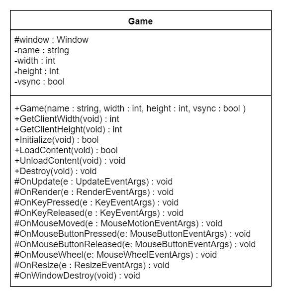
UML class diagram of the Game class.
The various functions of the Game class are described in the next section.
The Game Header
In this section, the interface for the Game class is described.
|
1 2 3 4 5 6 7 8 9 10 11 |
/** * @brief The Game class is the abstract base class for DirecX 12 demos. */ #pragma once #include <Events.h> #include <memory> // for std::enable_shared_from_this #include <string> // for std::wstring class Window; |
The Events.h header file included on line 6 contains structures that are used to relay window events back to the game class. An example of a window event that is fired on the Game class is the mouse and keyboard events that occur while the game’s window has focus.
The memory and string standard headers are also included on lines 8-9 to provide the std::enable_shared_from_this template and the std::wstring classes from the Standard Template Library (STL).
On line 11, the Window class is forward-declared in order to avoid including the header file for that class.
|
1 2 3 4 5 6 7 8 |
class Game : public std::enable_shared_from_this<Game> { public: /** * Create the DirectX demo using the specified window dimensions. */ Game(const std::wstring& name, int width, int height, bool vSync); virtual ~Game(); |
The constructor for the Game class takes the window title (name), and width and height of the render window to create. The vSync option specifies whether rendering should be synchronized to the vertical refresh rate of the screen or not.
|
1 2 3 4 5 6 7 8 9 10 11 12 13 14 15 16 17 18 19 |
/** * Initialize the DirectX Runtime. */ virtual bool Initialize(); /** * Load content required for the demo. */ virtual bool LoadContent() = 0; /** * Unload demo specific content that was loaded in LoadContent. */ virtual void UnloadContent() = 0; /** * Destroy any resource that are used by the game. */ virtual void Destroy(); |
The Game class provides several methods that can be overridden by a child class. The Game class provides a default implementation for the Initialize method which just creates a Window to render the graphics to and registers the window callback functions. The default implementation of the Destroy method just destroys the window. The implementations of the LoadContent and UnloadContent must be provided by the child class (which is also the subject of this lesson).
The Game class also provides several callback functions for window events which can be overridden by a child class. The default implementations for the window callback functions is to do nothing.
|
1 2 3 4 5 6 7 8 9 10 11 12 13 14 15 16 17 18 19 20 21 22 23 24 25 26 27 28 29 30 31 32 33 34 35 36 37 38 39 40 41 42 43 44 45 46 47 48 49 50 51 52 53 |
protected: friend class Window; /** * Update the game logic. */ virtual void OnUpdate(UpdateEventArgs& e); /** * Render stuff. */ virtual void OnRender(RenderEventArgs& e); /** * Invoked by the registered window when a key is pressed * while the window has focus. */ virtual void OnKeyPressed(KeyEventArgs& e); /** * Invoked when a key on the keyboard is released. */ virtual void OnKeyReleased(KeyEventArgs& e); /** * Invoked when the mouse is moved over the registered window. */ virtual void OnMouseMoved(MouseMotionEventArgs& e); /** * Invoked when a mouse button is pressed over the registered window. */ virtual void OnMouseButtonPressed(MouseButtonEventArgs& e); /** * Invoked when a mouse button is released over the registered window. */ virtual void OnMouseButtonReleased(MouseButtonEventArgs& e); /** * Invoked when the mouse wheel is scrolled while the registered window has focus. */ virtual void OnMouseWheel(MouseWheelEventArgs& e); /** * Invoked when the attached window is resized. */ virtual void OnResize(ResizeEventArgs& e); /** * Invoked when the registered window instance is destroyed. */ virtual void OnWindowDestroy(); |
The OnUpdate method declared on line 58 is invoked whenever the game logic should be updated. It is invoked when the WM_PAINT message is received by the Window.
The OnRender method is invoked whenever the screen should be redrawn. It is invoked immediately after the OnUpdate callback function.
The OnKeyPressed and OnKeyReleased callback functions are invoked whenever a key is pressed or released on the keyboard while the render window has focus.
The OnMouseMoved, On MouseButtonPressed, and OnMouseButtonReleased are invoked whenever the mouse moves, or any mouse button is pressed or released over the client area of the render window.
The OnMouseWheel callback function is invoked whenever the mouse wheel is scrolled while the mouse cursor is over the screen. In this case, the render windows does not need to have keyboard focus for this event to be dispatched to the window.
The OnResize method is invoked when the render window is resized. The implementation of the child class does not need to be concerned with resizing the swap chain buffers of the render window (this is handled automatically in the Window class) but does need to resize any resources that are allocated specifically by the derived class.
The OnWindowDestroy method is called when the render window is being destroyed. The default behaviour of this method is to call the UnloadContent method. A child class can override the OnWindowDestroy method if this is not intended behaviour.
The Game class also provides protected access to the window instance that is created by default in the Game::Initialize method.
|
1 2 3 4 5 6 7 8 9 |
std::shared_ptr<Window> m_pWindow; private: std::wstring m_Name; int m_Width; int m_Height; bool m_vSync; }; |
Most of the methods of the Game class do nothing. They simply provide a means to invoke the window callbacks from the window message process. The only exception to this is the Game::Initialize and Game::Destroy methods which create and destroy the render window instance.
Game::Initialize
The purpose of the Game::Initialize method is to initialize the game specific state. GPU resources should be allocated in the LoadContent method which should be provided by the child class.
|
1 2 3 4 5 6 7 8 9 10 11 12 13 14 15 |
bool Game::Initialize() { // Check for DirectX Math library support. if (!DirectX::XMVerifyCPUSupport()) { MessageBoxA(NULL, "Failed to verify DirectX Math library support.", "Error", MB_OK | MB_ICONERROR); return false; } m_pWindow = Application::Get().CreateRenderWindow(m_Name, m_Width, m_Height, m_vSync); m_pWindow->RegisterCallbacks(shared_from_this()); m_pWindow->Show(); return true; } |
Before utilizing any functions of the DirectX Math library, support for the CPU instruction sets on the end-users computer must be verified [7]. On line 23 the XMVerifyCPUSupport method is used to verify CPU support on the users computer. If CPU support is not available on the users computer, the function will return false and the Application’s Run method will return an error code.
On lines 29-30, a Window is created by the Application class and event callbacks are registered for the Game class.
Before the function returns, the Window is shown on line 31.
Game::Destroy
The default implementation of the Destroy method is simply to tell the application to destroy the render window that was created in the Game::Initialize method.
|
1 2 3 4 5 |
void Game::Destroy() { Application::Get().DestroyWindow(m_pWindow); m_pWindow.reset(); } |
The remaining methods of the Game class are empty and will be overridden by the demo class for this lesson.
Before delving into the details of the demo class for this lesson, it is important to understand some basic concepts about shaders.
Shaders
In order to implement the demo for this lesson, two shaders are required to perform the rendering.
- Vertex Shader
- Pixel Shader
The Vertex Shader is responsible for transforming the vertices of the object being rendered from object-space to clip-space. The clip-space vertices are required by the (fixed-function) Rasterizer Stage of the rendering pipeline in order to clip the rendering primitives against the view frustum and to compute the per-pixel (or per-fragment) attributes across the face of the rendered primitives. The interpolated vertex attributes are passed to the Pixel Shader in order to compute the final color of the pixel.
The Pixel Shader is responsible for computing the final color of the pixel that is rendered to the screen (or an offscreen render target). It receives the interpolated vertex attributes that are computed by the Rasterizer Stage and usually outputs at least one color value that is written to a render target. In this lesson, a very simple pixel shader is shown. In later lessons, more complex lighting equations will be used to create a more realistic rendering of a scene.
Vertex Shader
In this lesson, a simple vertex shader is discussed. This lesson is not intended to be an exhaustive description of how to write vertex shaders but to provide a basic understanding of how to write a simple vertex shader for the purpose of this lesson.
The basic concept of a vertex shader is that it receives the vertices that describe a model (expressed in object-space, or model-space) and performs zero or more transformations on the attributes of the vertices in order to produce the vertex attributes for the next stage of the rendering pipeline (this is usually the rasterizer stage but it could also be the geometry or tessellation stages).
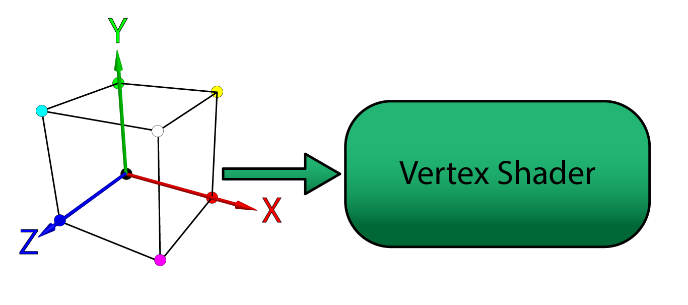
The model vertices in object-space are sent from the application to the vertex shader stage of the rendering pipeline.
A vertex can contain any number of attributes. For example, the vertex position is a possible attribute of a vertex. Vertex color, normal, or texture coordinate are other examples of vertex attributes. For this lesson, only vertex position and color are used as vertex attributes. In later lessons, the vertex normal and texture coordinates are used.
Vertex attributes can be sent to the GPU in either packed or interleaved format. Attributes that are stored in a packed format are usually stored in separate buffers (one buffer for position, another for color, etc..). Packed attributes are similar in concept to a Struct of Arrays (SoA).
Attributes that are stored in an interleaved format are usually stored in a single array. Interleaved attributes are similar in concept an Array of Structs (AoS). Although it is easier to think of vertices as an Array of Structs, it may actually be better for performance to store the attributes of a vertex as a Struct of Arrays especially if not all attributes are accessed in the vertex shader since fewer fetches to global memory are required and fetches can be better coalesced.
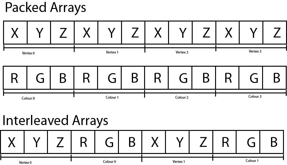
Packed versus Interleved arrays. Packed arrays store the vertex attributes in separate buffers while interleaved arrays store the vertex attributes interleaved in a single buffer.
How to specify the input layout of the vertex attributes is described later in the lesson.
Shader Symantics
The vertex shader can output one or more attributes to the next stage of the rendering pipeline but it must at least output a position attribute bound to the SV_Position system value semantic. Semantics are a way to tell the Input Assembler how to link the buffer data supplied by the application to the input parameters expected by the shader. Semantics are also the language syntax used to link output parameters from one shader stage to the input parameters to another shader stage.
In an HLSL shader the semantic name for the variable follows the colon (:) character in a variable declaration.
|
1 2 3 4 5 |
struct VertexPosColor { float3 Position : POSITION; float3 Color : COLOR; }; |
The snippet shows an example of a vertex definition in an HLSL shader. The VertexPosColor structure declares two member variables (vertex attributes):
PositionColor
The Position attribute is bound to the POSITION semantic and the Color attribute is bound to the COLOR semantic. These semantics will be used later to specify how the application data is bound to the vertex attributes in HLSL.
Position and Color attributes could be bound to FOO and BAR semantics but this would not be very descriptive for anyone else trying to read your code. The only requirement is that the input and output semantics match (and the types have to be convertible).Transformation and Spaces
In order to animate the object in the scene, a basic understanding of transformation and spaces must be established. If a refresher on transformation and spaces is needed, please refer to the articles titled Coordinate Systems, Matrices, and Understanding the View Matrix.
For this demo, an object is placed at the origin of the world and rotated. The camera is placed some distance away from the origin in order to view the object. The transformation matrix that rotates the object is called the model matrix and the transformation matrix to place the camera in the scene is called the view matrix. A final transformation called the projection matrix is also applied in order to transform the vertices from view space to clip space. These three matrices can be combined using matrix multiplication to produce a single matrix that can transform the vertices from objects space to clip space. This matrix is appropriately named the model-view-projection matrix or just MVP matrix.
The MVP matrix is required by the vertex shader to perform the transformations on the vertices of the model. This matrix is passed to the vertex shader using a ConstantBuffer object in HLSL.
|
1 2 3 4 5 6 |
struct ModelViewProjection { matrix MVP; }; ConstantBuffer<ModelViewProjection> ModelViewProjectionCB : register(b0); |
ConstantBuffer template construct in order to enable support for descriptor arrays. See Resource Binding in HLSL for more information. In HLSL the matrix type represents a 4×4 matrix (this is an alias of the float4x4 type). The ModelViewProjectionCB shader variable is bound to the b0 register. The b register type is reserved for constant buffer variables (see Shader Register & Register Spaces).
Vertex Shader Output
The vertex shader accepts vertex attributes passed from the application, transforms these inputs in zero or more ways (a vertex shader that performs no transformations on the input data is called a pass-through shader) and outputs the vertex attributes to be consumed by the next stage of the rendering pipeline. Just as the input attributes were bound to semantics, the output attributes are also bound to semantics.
|
1 2 3 4 5 |
struct VertexShaderOutput { float4 Color : COLOR; float4 Position : SV_Position; }; |
The VertexShaderOutput structure groups the vertex shader’s output attributes. The (arbitrarily named) COLOR semantic is used again to pass a Color attribute to the pixel shader stage.
The SV_Position system value semantic is a required semantic to be output by the vertex shader and it is the only required parameter that must be passed to the rasterizer stage. The parameter bound to the SV_Position system value semantic is not a required input parameter for the pixel shader and can be omitted from the pixel shader’s input parameters (as will be shown later). However, the byte offsets of the other parameters (in this case the Color parameter has an offset of 0 bytes within the VertexShaderOutput structure) must match between the outputs and inputs of linked shader stages. For this reason, the Position parameter is placed last in the VertexShaderOutput structure.
The Main Entry Point
The main entry point for the shader is a single function that takes the vertex attributes as input arguments and outputs the transformed vertex attributes.
|
1 2 3 4 5 6 7 8 9 |
VertexShaderOutput main(VertexPosColor IN) { VertexShaderOutput OUT; OUT.Position = mul(ModelViewProjectionCB.MVP, float4(IN.Position, 1.0f)); OUT.Color = float4(IN.Color, 1.0f); return OUT; } |
Unlike in GLSL, the name of the entry point function in HLSL is not required to be “main“. In fact, it is possible to define several entry-point functions in a single HLSL source file. The name of the entry point for the shader is specified when compiling the shader.
Each invocation of the vertex shader operates over a single vertex (as opposed to triangles or the entire mesh) and outputs the transformed vertex. Many vertices are processed in parallel and it is not possible to modify variables defined within the scope of the vertex shader and expect that other invocations of the vertex shader will see those changes (even if you declare the variable as static in the global scope of the vertex shader!). For example, you cannot declare a counter variable in the vertex shader and allow each invocation to increment that counter to see how many vertices were processed (you may be able to achieve this using atomic counters, but that is beyond the scope of this lesson).
On line 24, the vertex position is multiplied by the MVP matrix to produce the clip-space position. The input position must be cast to a float4 using a function-style cast in order to perform the multiplication because the MVP matrix is a 4×4 matrix. A 1.0 is appended to the last component of the position to ensure the matrix translation is taken into consideration.
0.0 was used in the last component of the vector, then the vector would be rotated but not translated.- If the vertex attribute is a position vector, then the 4th component of the vector must be a 1.
- If the vertex attribute is a normal vector, then the 4th component of the vector must be a 0.
Positional vectors are often referred to as points (because it represents a point in space). Directional vectors are simply referred to as vectors.
On line 25 the input Color attribute is passed to the output Color attribute of the OUT variable. The output color also expects a float4 to be used as output so the function-style cast is used again. In this case, the final component is set to 1.0. The last component in a color value is often referred to as the alpha (α) which in most cases is interpreted as the opacity of the color (but this is not a requirement). Since alpha blending is not used for this example, the final component of the color attribute has absolutely no impact on the final output color of the pixel shader (try setting this value to 0.0 and observe the result).
On line 27, the OUT parameter is returned and the result is passed as input to the Rasterizer stage. The rasterizer will use the Position parameter to determine the pixel’s coordinates (in screen space, by applying the viewport), the depth value (in normalized-device coordinate space) which is written to the depth buffer, and the interpolated Color parameter is passed as input to the pixel shader stage.
The entire listing for the vertex shader is shown below.
|
1 2 3 4 5 6 7 8 9 10 11 12 13 14 15 16 17 18 19 20 21 22 23 24 25 26 27 28 |
struct ModelViewProjection { matrix MVP; }; ConstantBuffer<ModelViewProjection> ModelViewProjectionCB : register(b0); struct VertexPosColor { float3 Position : POSITION; float3 Color : COLOR; }; struct VertexShaderOutput { float4 Color : COLOR; float4 Position : SV_Position; }; VertexShaderOutput main(VertexPosColor IN) { VertexShaderOutput OUT; OUT.Position = mul(ModelViewProjectionCB.MVP, float4(IN.Position, 1.0f)); OUT.Color = float4(IN.Color, 1.0f); return OUT; } |
Pixel Shader
The purpose of the pixel shader is to produce the final color that should be written to the currently bound render target(s). The pixel shader can write to a maximum of eight color targets and one depth target. For this example, only a single color render target and a single depth target are bound to the output merger stage.
The pixel shader takes the interpolated color value from the Rasterizer stage and outputs that color to the only bound render target using the SV_Target system value semantic.
|
1 2 3 4 5 6 7 8 9 |
struct PixelShaderInput { float4 Color : COLOR; }; float4 main( PixelShaderInput IN ) : SV_Target { return IN.Color; } |
You may notice that the pixel shader is not using the Position attribute that was computed in the vertex shader. Only the Color attribute is used and therefore the Position parameter can be omitted from the PixelShaderInput structure.
The main entry point for the pixel shader is called main (but it is not necessary to call the entry-point function main) and it takes the PixelShaderInput as an input parameter and outputs a single color. This is the simplest form of a pixel shader (actually, no pixel shader would be simpler – it is valid to define a graphics pipeline state without a pixel shader if you only need depth information).
The Tutorial Class
The Tutorial class (actually Tutorial2 since this is the 2nd tutorial in this series) is derived from the Game class described earlier in this lesson. Besides overriding the LoadContent and UnloadContent pure virtual functions from the Game class, the Tutorial2 class also provides a few helper functions in order to upload vertex and index data to the GPU and perform resource transitioning. Resource transitions have been introduced in the previous lesson but uploading resources to the GPU is a new concept that hasn’t been introduced yet. The Tutorial2 class will also load the shaders, define the input layout, create the root signature and pipeline state object.
The Tutorial Header
Before showing any source code, the Tutorial2.h header file is first described in order to provide some background for the functions that are described in more detail in the following sections.
|
1 2 3 4 5 6 |
#pragma once #include <Game.h> #include <Window.h> #include <DirectXMath.h> |
The Tutorial2 class has a dependency on the Game class which is declared in the Game.h header file included on line 3. The Window class is declared in the Window.h header file (not to be confused with the Windows.h header file which contains the Win32 programming APIs).
The DirectXMath.h header file is included in the Window 10 SDK and is considered to be part of the DirectX APIs [7]. This header includes the vector and matrix definitions that are used to define the model, camera, and projection transformation matrices for the demo.
|
1 2 3 4 5 6 7 8 9 10 11 12 13 14 15 |
class Tutorial2 : public Game { public: using super = Game; Tutorial2(const std::wstring& name, int width, int height, bool vSync = false); /** * Load content required for the demo. */ virtual bool LoadContent() override; /** * Unload demo specific content that was loaded in LoadContent. */ virtual void UnloadContent() override; |
The constructor for the Tutorial2 class declared on line 13 is similar to that of the Game class. The name parameter defines the window title for the render window. The width and height parameters define how large the window is when it is created. The vSync option determines if the renderer should synchronize with vertical refresh rate of the screen.
The LoadContent and UnloadContent functions override the pure virtual functions from the Game class that was described previously.
|
1 2 3 4 5 6 7 8 9 10 11 12 13 14 15 16 17 18 19 20 21 22 23 24 |
protected: /** * Update the game logic. */ virtual void OnUpdate(UpdateEventArgs& e) override; /** * Render stuff. */ virtual void OnRender(RenderEventArgs& e) override; /** * Invoked by the registered window when a key is pressed * while the window has focus. */ virtual void OnKeyPressed(KeyEventArgs& e) override; /** * Invoked when the mouse wheel is scrolled while the registered window has focus. */ virtual void OnMouseWheel(MouseWheelEventArgs& e) override; virtual void OnResize(ResizeEventArgs& e) override; |
The OnUpdate method is invoked whenever the game logic needs to be updated and the OnRender method is invoked whenever the game screen needs to be drawn.
The OnKeyPressed and OnMouseWheel events are invoked from the Window class whenever a key is pressed, or the mouse wheel is moved while the game Window has focus.
The OnResize method is called whenever the render window is resized (for example, if the window is toggled between fullscreen states).
The Tutorial2 class also defines a few helper functions.
|
1 2 3 4 5 6 7 8 9 10 11 12 13 14 15 16 17 18 19 20 21 22 23 |
private: // Helper functions // Transition a resource void TransitionResource(Microsoft::WRL::ComPtr<ID3D12GraphicsCommandList2> commandList, Microsoft::WRL::ComPtr<ID3D12Resource> resource, D3D12_RESOURCE_STATES beforeState, D3D12_RESOURCE_STATES afterState); // Clear a render target view. void ClearRTV(Microsoft::WRL::ComPtr<ID3D12GraphicsCommandList2> commandList, D3D12_CPU_DESCRIPTOR_HANDLE rtv, FLOAT* clearColor); // Clear the depth of a depth-stencil view. void ClearDepth(Microsoft::WRL::ComPtr<ID3D12GraphicsCommandList2> commandList, D3D12_CPU_DESCRIPTOR_HANDLE dsv, FLOAT depth = 1.0f ); // Create a GPU buffer. void UpdateBufferResource(Microsoft::WRL::ComPtr<ID3D12GraphicsCommandList2> commandList, ID3D12Resource** pDestinationResource, ID3D12Resource** pIntermediateResource, size_t numElements, size_t elementSize, const void* bufferData, D3D12_RESOURCE_FLAGS flags = D3D12_RESOURCE_FLAG_NONE ); // Resize the depth buffer to match the size of the client area. void ResizeDepthBuffer(int width, int height); |
The functionality of the TransitionResource and ClearRTV methods were described in the previous lesson. The ClearDepth method is very similar to the ClearRTV method except it is used to clear a depth-stencil view (DSV) instead of a render target view (RTV).
The UpdateBufferResource method is used to both create a resource large enough to hold the buffer data, but it will also create an intermediate upload buffer that is used to transfer the buffer data from CPU memory into GPU memory. The intermediate upload buffer needs to be resident until the graphics command list is finished uploading that resource to the destination buffer in GPU memory. For that reason, the pointers returned by this function cannot be destroyed until the resource has been fully uploaded to the destination resource.
The ResizeDepthBuffer method is used to resize the depth buffer that is used by the demo. The depth buffer ensures that geometry that appears further away from the viewer is properly occluded by geometry that appears closer to the viewer. The depth buffer is not owned by the Window class (together with the swap chain) because the depth buffer is not a required resource in order to display the final rendered image on the screen.

The depth buffer stores the depth of the pixel in normalized device coordinate space (0 – 1). Depth values far away appear white (1.0) and depth values close to the viewer appear darker (0.0).
The depth buffer stores the depth of the pixel in normalized device coordinate space (NDC). Only pixels that are not occluded based on the current value in the depth buffer are drawn. This ensures that primitives that are further away from the viewer are not drawn on top of primitives that are closer to the viewer.
|
1 |
uint64_t m_FenceValues[Window::BufferCount] = {}; |
In order to perform correct synchronization, the Tutorial2 class needs to track the fence values for each rendered frame. The number of frames that need to be tracked is stored in the Window::BufferCount static constant.
In order to demonstrate a basic rendering pipeline, a cube is rendered using a vertex buffer and index buffer. For each of these resources, a view is created which describes the buffer resources to the rendering pipeline.
|
1 2 3 4 5 6 |
// Vertex buffer for the cube. Microsoft::WRL::ComPtr<ID3D12Resource> m_VertexBuffer; D3D12_VERTEX_BUFFER_VIEW m_VertexBufferView; // Index buffer for the cube. Microsoft::WRL::ComPtr<ID3D12Resource> m_IndexBuffer; D3D12_INDEX_BUFFER_VIEW m_IndexBufferView; |
The VertexBuffer resource is used to store the vertex buffer geometry for the cube and the IndexBuffer resource is used to store the index data to render the cube.
|
1 2 3 4 |
// Depth buffer. Microsoft::WRL::ComPtr<ID3D12Resource> m_DepthBuffer; // Descriptor heap for depth buffer. Microsoft::WRL::ComPtr<ID3D12DescriptorHeap> m_DSVHeap; |
The depth buffer is stored in the m_DepthBuffer member variable. Similar to the render target views for the swap chain, the depth buffer requires a depth-stencil view. The depth-stencil view is created in a descriptor heap.
|
1 2 3 4 5 6 7 8 |
// Root signature Microsoft::WRL::ComPtr<ID3D12RootSignature> m_RootSignature; // Pipeline state object. Microsoft::WRL::ComPtr<ID3D12PipelineState> m_PipelineState; D3D12_VIEWPORT m_Viewport; D3D12_RECT m_ScissorRect; |
The root signature describes the parameters passed to the various stages of the rendering pipeline and the pipeline state object describes the rendering pipeline itself.
The viewport and scissor rect variables are used to initialize the rasterizer stage of the rendering pipeline.
|
1 2 3 4 5 6 7 8 |
float m_FoV; DirectX::XMMATRIX m_ModelMatrix; DirectX::XMMATRIX m_ViewMatrix; DirectX::XMMATRIX m_ProjectionMatrix; bool m_ContentLoaded; }; |
The m_FoV variable is used to store the current field of view of the camera. For this demo, the middle mouse wheel is used to “zoom-in” to the cube in the center of the scene.
The model, view and projection matrices are used to compute the MVP matrix that is used in the vertex shader to rotate the cube, position the camera, and project the vertices into clip-space.
The m_ContentLoaded is used to indicate when the game content has been loaded.
The implementation details for the Tutorial2 class is described next.
Tutorial2 Preamble
The preamble for the Tutorial2 source file contains the required header files for the class.
|
1 2 3 4 5 6 7 8 9 10 11 12 13 14 15 16 17 18 19 20 21 22 23 |
#include <Tutorial2.h> #include <Application.h> #include <CommandQueue.h> #include <Helpers.h> #include <Window.h> #include <wrl.h> using namespace Microsoft::WRL; #include <d3dx12.h> #include <d3dcompiler.h> #include <algorithm> // For std::min and std::max. #if defined(min) #undef min #endif #if defined(max) #undef max #endif using namespace DirectX; |
The Tutorial2.h header file included on line 1 is described in the previous section.
The Application.h header file included on line 3 contains the definition of the Application class. The Application class was briefly described earlier in this post but not described in full details. The Application class is used to create Window instances for displaying the rendered image.
The CommandQueue.h header file contains the definition of the CommandQueue class that was described in detail in the section titled Command Queue.
The Helpers.h header file contains helper functions and macros that are used throughout the demo source code.
The Window.h header file contains the Window class definition (not to be mistaken with the Windows.h WIN32 API header file).
The wrl.h header file contains the Windows Runtime C++ Template Library. It is required for the ComPtr template class.
The d3dx12.h header file included on line 11 is not considered to be part of the standard DirectX 12 API and must be downloaded separately from the Microsoft GitHub page (https://github.com/Microsoft/DirectX-Graphics-Samples/blob/master/Libraries/D3DX12/d3dx12.h).
The d3dcompiler.h header file contains functions that are required to load (precompiled) shaders from disc.
D3DCompiler functions, do not forget to link against the D3Dcompiler_47.lib library and copy the D3dcompiler_47.dll to the same folder as the binary executable when distributing your project.A redistributable version of the D3dcompiler_47.dll file can be found in the Windows 10 SDK installation folder at
For more information, refer to the MSDN blog post at: https://blogs.msdn.microsoft.com/chuckw/2012/05/07/hlsl-fxc-and-d3dcompile/
The algorithm STL header file included on line 14 contains the std::min and std::max functions.
In order to disambiguate the min and max global macros defined in some Windows header file somewhere, the min and max macros are undefined on lines 15-21.
In order to avoid polluting the global namespace, all of the DirectX Math types are declared in the DirectX namespace. To avoid having to type “DirectX::” for all DirectX math types, the DirectX namespace is imported into the current source file on line 23.
Starting with the C++17 standard, the algorithm header file also contains the clamp function. Until C++17 standard is fully implemented in Visual Studio, an implementation of the clamp function will need to be provided manually 😭.
|
1 2 3 4 5 6 |
// Clamp a value between a min and max range. template<typename T> constexpr const T& clamp(const T& val, const T& min, const T& max) { return val < min ? min : val > max ? max : val; } |
For this lesson, each vertex will have only 2 attributes:
- Position
- Color
Both the Position and Color vertex attributes are stored as 3-component 32-bit floating-point vectors. Vertices are stored using an interleaved storage format (described previously).
|
1 2 3 4 5 6 |
// Vertex data for a colored cube. struct VertexPosColor { XMFLOAT3 Position; XMFLOAT3 Color; }; |
The VertexPosColor structure is used to group the vertex attributes to be passed to the vertex shader.
Try to convert this demo to using packed vertex formats instead of interleaved vertex formats. Try to draw the mesh 1,000 or 10,000 times. Do you notice a performance difference? Is it better or worse than using interleaved vertex formats?
Next, the vertex data for the cube mesh is defined.
|
1 2 3 4 5 6 7 8 9 10 |
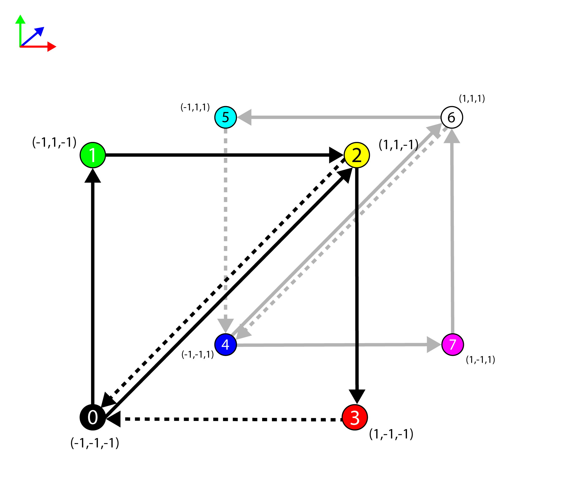
static VertexPosColor g_Vertices[8] = { { XMFLOAT3(-1.0f, -1.0f, -1.0f), XMFLOAT3(0.0f, 0.0f, 0.0f) }, // 0 { XMFLOAT3(-1.0f, 1.0f, -1.0f), XMFLOAT3(0.0f, 1.0f, 0.0f) }, // 1 { XMFLOAT3( 1.0f, 1.0f, -1.0f), XMFLOAT3(1.0f, 1.0f, 0.0f) }, // 2 { XMFLOAT3( 1.0f, -1.0f, -1.0f), XMFLOAT3(1.0f, 0.0f, 0.0f) }, // 3 { XMFLOAT3(-1.0f, -1.0f, 1.0f), XMFLOAT3(0.0f, 0.0f, 1.0f) }, // 4 { XMFLOAT3(-1.0f, 1.0f, 1.0f), XMFLOAT3(0.0f, 1.0f, 1.0f) }, // 5 { XMFLOAT3( 1.0f, 1.0f, 1.0f), XMFLOAT3(1.0f, 1.0f, 1.0f) }, // 6 { XMFLOAT3( 1.0f, -1.0f, 1.0f), XMFLOAT3(1.0f, 0.0f, 1.0f) } // 7 }; |
The g_Vertices static arrays defines the unique vertices that make up the cube. The image below represents the various vertices for the mesh.
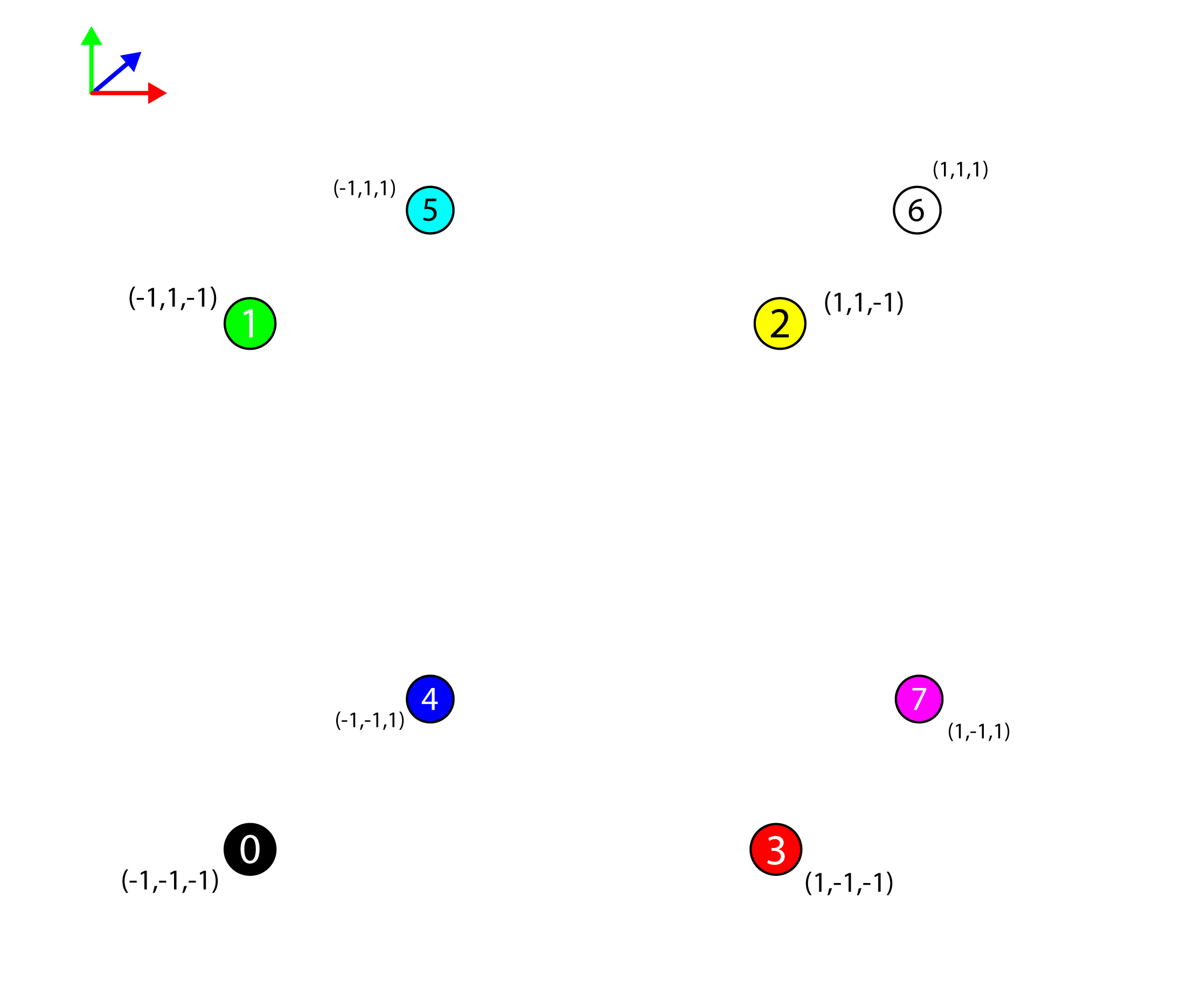
The 8 vertices of the cube mesh represented in 3D space.
The vertices by themselves are not sufficient to represent a solid cube mesh in 3D space. The Input Assembler stage of the rendering pipeline can render a set of one or more points, but points alone cannot be used to generate solid geometry.
The Input Assembler stage of the rendering pipeline understands the following primitive types [8]:
Primitive Topologies in DirectX 12
The D3D_PRIMITIVE_TOPOLOGY enumeration specifies how the Input Assembler stage interprets the vertex data that is bound to the rendering pipeline.
D3D_PRIMITIVE_TOPOLOGY_POINTLIST: A disconnected list of points.D3D_PRIMITIVE_TOPOLOGY_LINELIST: A list of disconnected lines.D3D_PRIMITIVE_TOPOLOGY_LINESTRIP: A list of connected lines.D3D_PRIMITIVE_TOPOLOGY_TRIANGLELIST: A list of disconnected triangles.D3D_PRIMITIVE_TOPOLOGY_TRIANGLESTRIP: A list of connected triangles. Vertex \(n\) and vertex \(n-2, \forall n>1\) are implicitly connected to form the triangles.D3D_PRIMITIVE_TOPOLOGY_LINELIST_ADJ: A list of disconnected lines. Additional adjacency information is available to the Geometry shader stage.D3D_PRIMITIVE_TOPOLOGY_LINESTRIP_ADJ: A list of connected lines. Additional adjacency information is available to the Geometry shader stage.D3D_PRIMITIVE_TOPOLOGY_TRIANGLELIST_ADJ: A list of disconnected triangles. Additional adjacency information is available to the Geometry shader stage.D3D_PRIMITIVE_TOPOLOGY_TRIANGRIP_ADJ: A list of connected triangles. Additional adjacency information is available to the Geometry shader stage.
Points and lines cannot be used to generate a solid mesh (where the faces of the mesh are shaded in). Only triangles (and patches) can be used to generate a shaded mesh. For this example, the mesh is going to be generated from a list of triangles. In order to tell the Input Assembler stage how to generate the triangles for the mesh, an index buffer is used.
|
1 2 3 4 5 6 7 8 9 |
static WORD g_Indicies[36] = { 0, 1, 2, 0, 2, 3, 4, 6, 5, 4, 7, 6, 4, 5, 1, 4, 1, 0, 3, 2, 6, 3, 6, 7, 1, 5, 6, 1, 6, 2, 4, 0, 3, 4, 3, 7 }; |
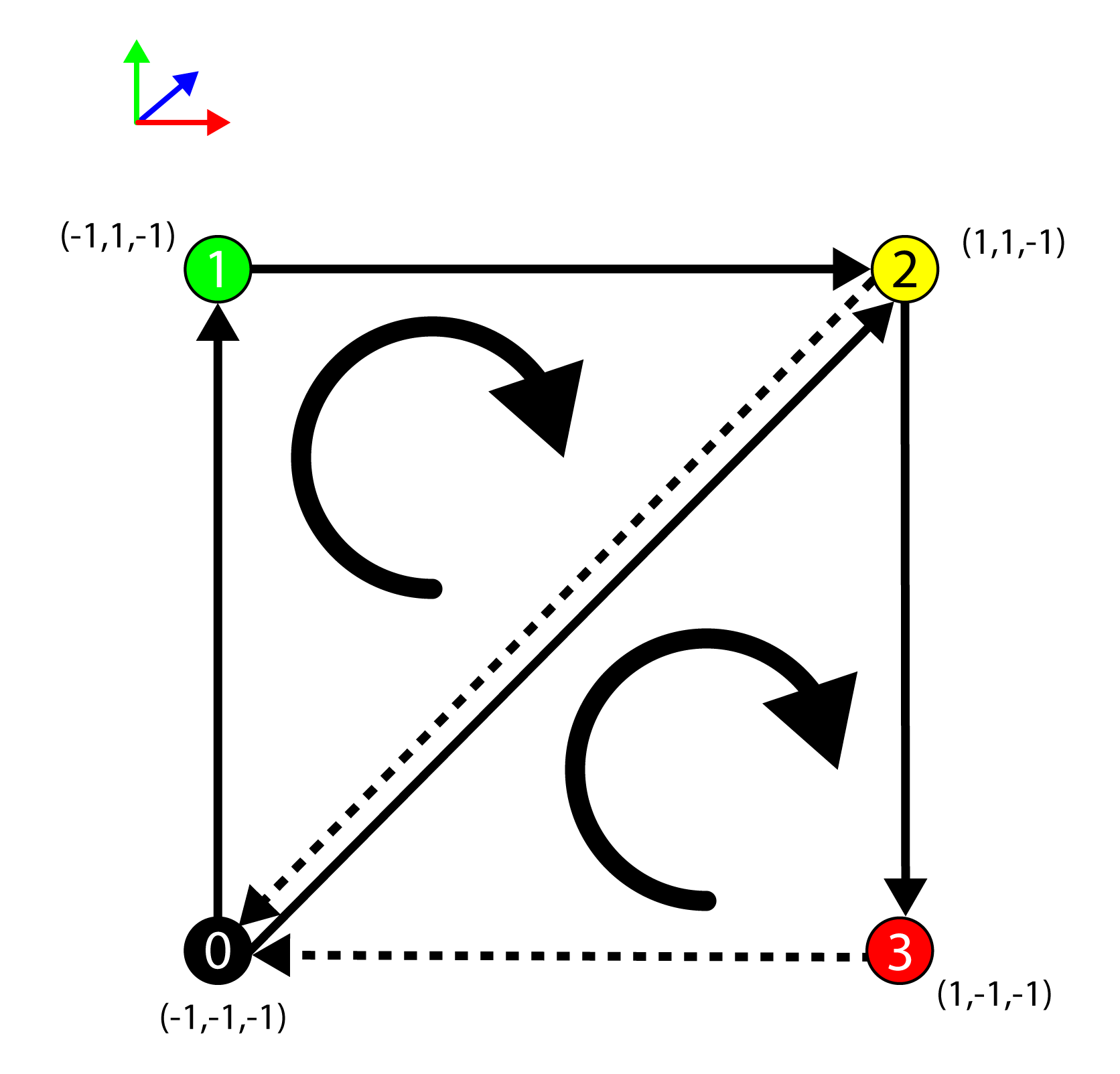
The g_Indicies array defines the index buffer that is used to represent the triangles that are used to create the solid cube. The values in the index buffer represent the index of the vertex in the vertex buffer (the g_Vertices array). The cube consists of 6 faces. Each face is composed of 2 triangles. The g_Indicies array contains 36 indices (3 indices per triangle). The image below shows only the first two faces of the cube.
The vertices of the cube with the front and back faces shown with triangles.
Only the front and back sides of the cube are shown in the image above (the top, bottom, left, and right sides are excluded from the image to keep it more clear). The edges of the back facing triangles are shown in a light gray while the edges of the front facing triangles are shown in black. A front-facing polygon is said to be facing the viewer while a back-facing polygon is said to be facing away from the viewer.
Since back-facing polygons are generally not visible to the viewer (assuming the mesh is fully convex and the material is not transparent) then it is not efficient to shade the pixels that will not be visible in the final render. As an optimization, it is possible to tell the Rasterizer stage to cull (remove from the rendering pipeline) back-facing polygons.
The winding-order of the triangle is used to determine if it is front-facing or back-facing. The winding order is determined by the direction of the normal of the triangle (in projected clip-space). The normal for the triangle is based on the cross-product of two edges of the triangle. Winding order can be either clockwise or counter-clockwise. The default winding order for front-facing polygons in DirectX is clockwise (so back-facing polygons are counter-clockwise).
The winding order for front-facing polygons is clockwise.
To determine if a triangle is front-facing, the direction of the normal is computed by taking the cross product of the edges of the triangle (in projected clip-space). The normal \(\mathbf{n}\) of the triangle formed by the vertices \(\mathbf{a}\), \(\mathbf{b}\), and \(\mathbf{c}\) is:
\[
\begin{array}{rcl}
\mathbf{u} & = & \mathbf{b}-\mathbf{a} \\
\mathbf{v} & = & \mathbf{c}-\mathbf{a} \\
\mathbf{n} & = & \mathbf{u}\times\mathbf{v} \\
\end{array}
\]
In projected clip space, the \(z\) component of the resulting normal is negative if it is facing the viewer. Since it is sufficient to know if the direction of the \(z\) component of the normal is positive or negative, the equation can be reduced to:
\[
\mathbf{n}_z=(\mathbf{u}_x\mathbf{v}_y)-(\mathbf{u}_y\mathbf{v}_x)
\]
The triangle is front-facing if \(\mathbf{n}_z\lt 0\) and back-facing otherwise.
Tutorial2::Tutorial2
The constructor for the Tutorial2 class simply passes the initialization variables to the parent class (Game). It also initializes the scissor, viewport and field of view (fov) variables.
|
1 2 3 4 5 6 7 8 |
Tutorial2::Tutorial2( const std::wstring& name, int width, int height, bool vSync ) : super(name, width, height, vSync) , m_ScissorRect(CD3DX12_RECT(0, 0, LONG_MAX, LONG_MAX)) , m_Viewport(CD3DX12_VIEWPORT(0.0f, 0.0f, static_cast<float>(width), static_cast<float>(height))) , m_FoV(45.0) , m_ContentLoaded(false) { } |
The m_ScissorRect is used to mask out a rectangular region of the screen that will allow for rendering. In previous versions of DirectX, it was not necessary to explicitly specify a scissor rectangle before rendering. Since DirectX 12, the programmer must explicitly specify a scissor rectangle. Initializing the scissor rectangle to {0, 0, LONG_MAX, LONG_MAX} ensures that the scissor rectangle covers the entire screen regardless of the size of the screen. If the screen is resized, the scissor rectangle does not need to be updated.
The m_Viewport specifies the viewable part of the screen to render to. The viewport can be smaller than the size of the screen (this is common when implementing split-screen rendering) but it should not be larger than the rendertarget that is bound to the output merger stage. The viewport is specified on the rasterizer stage and it is used to tell the rasterizer how to transform the vertices from normalized device coordinate space (NDC) into screen space which is required for the pixel shader.
The m_FoV variable represents the vertical field of view of the camera. It is initialized to 45° but it can be adjusted at runtime using the mouse wheel (as will be shown later).
Tutorial2::UpdateBufferResource
The UpdateBufferResource method is used to create a ID3D12Resource that is large enough to store the buffer data passed to the function and to create an intermediate buffer that is used to copy the CPU buffer data to the GPU. For this demo, the UpdateBufferResource method is used to initialize the vertex buffer and index buffer resources.
|
1 2 3 4 5 6 7 |
void Tutorial2::UpdateBufferResource( ComPtr<ID3D12GraphicsCommandList2> commandList, ID3D12Resource** pDestinationResource, ID3D12Resource** pIntermediateResource, size_t numElements, size_t elementSize, const void* bufferData, D3D12_RESOURCE_FLAGS flags ) { |
The commandList argument is required to transfer the buffer data to the destination resource.
The pDestinationResource and the pIntermediateResource pointers are used to store the destination and intermediate resources that are created in this method.
The numElements, elementSize, and bufferData arguments refer to the CPU buffer data that is transferred to the GPU resource.
The flags argument is used to specify any additional flags that are required to create the buffer resource.
|
1 2 3 |
auto device = Application::Get().GetDevice(); size_t bufferSize = numElements * elementSize; |
On line 75, the DirectX 12 device is queried from the Application class.
The bufferSize variable is size of the buffer in bytes.
The next step is to create a GPU resource in committed memory that is large enough to store the buffer.
|
1 2 3 4 5 6 7 8 |
// Create a committed resource for the GPU resource in a default heap. ThrowIfFailed(device->CreateCommittedResource( &CD3DX12_HEAP_PROPERTIES(D3D12_HEAP_TYPE_DEFAULT), D3D12_HEAP_FLAG_NONE, &CD3DX12_RESOURCE_DESC::Buffer(bufferSize, flags), D3D12_RESOURCE_STATE_COMMON, nullptr, IID_PPV_ARGS(pDestinationResource))); |
The ID3D12Device::CreateCommittedResource method is used to create a resource and an implicit heap that is large enough to store the resource. The resource is also mapped to the implicit heap.
The ID3D12Device::CreateCommittedResource has the following signature [9]:
|
1 2 3 4 5 6 7 8 9 |
HRESULT CreateCommittedResource( [in] const D3D12_HEAP_PROPERTIES *pHeapProperties, D3D12_HEAP_FLAGS HeapFlags, [in] const D3D12_RESOURCE_DESC *pDesc, D3D12_RESOURCE_STATES InitialResourceState, [in, optional] const D3D12_CLEAR_VALUE *pOptimizedClearValue, REFIID riidResource, [out, optional] void **ppvResource ); |
And takes the following arguments:
D3D12_HEAP_PROPERTIES *pHeapProperties: A pointer to aD3D12_HEAP_PROPERTIESstructure that provides properties for the resource’s heap.D3D12_HEAP_FLAGS HeapFlags: Heap options, as a bitwise-OR’d combination ofD3D12_HEAP_FLAGSenumeration constants.D3D12_RESOURCE_DESC *pDesc: A pointer to aD3D12_RESOURCE_DESCstructure that describes the resource.D3D12_RESOURCE_STATES InitialResourceState: The initial state of the resource, as a bitwise-OR’d combination ofD3D12_RESOURCE_STATESenumeration constants.
When a resource is created together with aD3D12_HEAP_TYPE_UPLOADheap,InitialResourceStatemust beD3D12_RESOURCE_STATE_GENERIC_READ. When a resource is created together with aD3D12_HEAP_TYPE_READBACKheap,InitialResourceStatemust beD3D12_RESOURCE_STATE_COPY_DEST.D3D12_CLEAR_VALUE *pOptimizedClearValue: Specifies aD3D12_CLEAR_VALUEthat describes the default value for a clear color.
pOptimizedClearValuespecifies a value for which clear operations are most optimal. When the created resource is a texture with either theD3D12_RESOURCE_FLAG_ALLOW_RENDER_TARGETorD3D12_RESOURCE_FLAG_ALLOW_DEPTH_STENCILflags, applications should choose the value that the clear operation will most commonly be called with. Clear operations can be called with other values, but those operations will not be as efficient as when the value matches the one passed into resource creation.pOptimizedClearValuemust beNULLwhen used withD3D12_RESOURCE_DIMENSION_BUFFER.REFIID riidResource: The globally unique identifier (GUID) for the resource interface. This is an input parameter. TheREFIID, or GUID, of the interface to the resource can be obtained by using the__uuidof()macro. For example,__uuidof(ID3D12Resource)will get the GUID of the interface to a resource.void **ppvResource: A pointer to memory that receives the requested interface pointer to the created resource object.ppvResourcecan beNULL, to enable capability testing. WhenppvResourceisNULL, no object will be created andS_FALSEwill be returned (whenpResourceDescis valid).
On lines 82-88, the default resource is created but the buffer data is not yet uploaded to that resource. The next step is to create another resource that is used to transfer the CPU buffer data into GPU memory. To perform the memory transfer, an intermediate buffer resource is created using an upload heap.
|
1 2 3 4 5 6 7 8 9 10 |
// Create an committed resource for the upload. if (bufferData) { ThrowIfFailed(device->CreateCommittedResource( &CD3DX12_HEAP_PROPERTIES(D3D12_HEAP_TYPE_UPLOAD), D3D12_HEAP_FLAG_NONE, &CD3DX12_RESOURCE_DESC::Buffer(bufferSize), D3D12_RESOURCE_STATE_GENERIC_READ, nullptr, IID_PPV_ARGS(pIntermediateResource))); |
If the buffer data isn’t NULL then another committed resource is created using the ID3D12Device::CreateCommittedResource method. In this case, the heap type is set to D3D12_HEAP_TYPE_UPLOAD and the resource state is initailly set to D3D12_RESOURCE_STATE_GENERIC_READ.
D3D12_HEAP_TYPE_UPLOAD heap must be created with D3D12_RESOURCE_STATE_GENERIC_READ and cannot be changed away from this.With the destination and intermediate resources created, the CPU buffer data can be transferred to the GPU resources.
|
1 2 3 4 5 6 7 8 9 10 |
D3D12_SUBRESOURCE_DATA subresourceData = {}; subresourceData.pData = bufferData; subresourceData.RowPitch = bufferSize; subresourceData.SlicePitch = subresourceData.RowPitch; UpdateSubresources(commandList.Get(), *pDestinationResource, *pIntermediateResource, 0, 0, 1, &subresourceData); } } |
The D3D12_SUBRESOURCE_DATA structure is used to describe the subresource data that is to be uploaded to the GPU resource.
This structure has the following syntax [10]:
|
1 2 3 4 5 |
typedef struct D3D12_SUBRESOURCE_DATA { const void *pData; LONG_PTR RowPitch; LONG_PTR SlicePitch; } D3D12_SUBRESOURCE_DATA; |
And has the following members:
void *pData: A pointer to a memory block that contains the subresource data.LONG_PTR RowPitch: The row pitch, or width, or physical size, in bytes, of the subresource data.LONG_PTR SlicePitch: The depth pitch, or width, or physical size, in bytes, of the subresource data.
On line 106-109, the UpdateSubresources function is used to upload the CPU buffer data to the GPU resource in a default heap using an intermediate buffer in an upload heap.
The UpdateSubresources method has the following signature [11]:
|
1 2 3 4 5 6 7 8 9 |
UINT64 inline UpdateSubresources( _In_ ID3D12GraphicsCommandList *pCmdList, _In_ ID3D12Resource *pDestinationResource, _In_ ID3D12Resource *pIntermediate, UINT64 IntermediateOffset, _In_ UINT FirstSubresource, _In_ UINT NumSubresources, _In_ D3D12_SUBRESOURCE_DATA *pSrcData ); |
And takes the following arguments:
ID3D12GraphicsCommandList *pCmdList: A pointer to theID3D12GraphicsCommandListinterface for the command list.ID3D12Resource *pDestinationResource: A pointer to theID3D12Resourceinterface that represents the destination resource.ID3D12Resource *pIntermediate: A pointer to theID3D12Resourceinterface that represents the intermediate resource.UINT64 IntermediateOffset: The offset, in bytes, to the intermediate resource.UINT FirstSubresource: The index of the first subresource in the resource. The range of valid values is 0 toD3D12_REQ_SUBRESOURCES.UINT NumSubresources: The number of subresources in the resource to be updated. The range of valid values is 0 to (D3D12_REQ_SUBRESOURCES–FirstSubresource).D3D12_SUBRESOURCE_DATA *pSrcData: Pointer to an array (of lengthNumSubresources) of pointers toD3D12_SUBRESOURCE_DATAstructures containing descriptions of the subresource data used for the update.
For buffer resources, the FirstSubresource is always 0 and the NumSubresources is always 1 (or 0, but then this function does nothing) because buffers only have a single subresource at index 0.
Tutorial2::LoadContent
The LoadContent function is used to load all of the content that is required by the demo. In summary, the LoadContent function will perform the following steps:
- Upload the Vertex buffer data for a cube mesh
- Create a vertex buffer view
- Upload the index buffer data for a cube mesh
- Create an index buffer view
- Create a descriptor heap for the depth-stencil view
- Load the vertex shader
- Load the pixel shader
- Create the input layout for the vertex shader
- Create a root signature
- Create a graphics pipeline state object (PSO)
- Create a depth buffer
The vertex buffer data and index buffer data require a ID3D12GraphicsCommandList to perform the copy operation. Creating and retrieving command lists was described in the Command Queue Class section above. The LoadContent function uses the (copy) CommandQueue class to retrieve a command list that can be used to upload the buffer data to the GPU resources.
|
1 2 3 4 5 |
bool Tutorial2::LoadContent() { auto device = Application::Get().GetDevice(); auto commandQueue = Application::Get().GetCommandQueue(D3D12_COMMAND_LIST_TYPE_COPY); auto commandList = commandQueue->GetCommandList(); |
On line 116 the D3D12_COMMAND_LIST_TYPE_COPY command queue is retrieved from the Application instance. On line 117 a ID3D12GraphicsCommandList is retrieved from the CommandQueue.
Next, the buffer data is copied to the GPU resources.
Upload Vertex Buffer
The Tutorial2::UpdateBufferResource method described earlier is used to create the GPU resources and upload the vertex buffer data to the GPU.
|
1 2 3 4 5 |
// Upload vertex buffer data. ComPtr<ID3D12Resource> intermediateVertexBuffer; UpdateBufferResource(commandList.Get(), &m_VertexBuffer, &intermediateVertexBuffer, _countof(g_Vertices), sizeof(VertexPosColor), g_Vertices); |
The intermediateVertexBuffer is the temporary vertex buffer resource that is used to transfer the CPU vertex buffer data to the GPU. The m_VertexBuffer member variable is the destination resource for the vertex buffer data and is used for rendering the cube geometry.
The g_Vertices global variable is declared on line 40 and contains the vertices in CPU memory for the cube geometry.
Vertex Buffer View
A D3D12_VERTEX_BUFFER_VIEW structure is used to tell the Input Assembler stage where the vertices are stored in GPU memory.
|
1 2 3 4 |
// Create the vertex buffer view. m_VertexBufferView.BufferLocation = m_VertexBuffer->GetGPUVirtualAddress(); m_VertexBufferView.SizeInBytes = sizeof(g_Vertices); m_VertexBufferView.StrideInBytes = sizeof(VertexPosColor); |
The m_VertexBufferView member variable is the D3D12_VERTEX_BUFFER_VIEW structure that describes the vertex buffer. The D3D12_VERTEX_BUFFER_VIEW structure has the following syntax [12]:
|
1 2 3 4 5 |
typedef struct D3D12_VERTEX_BUFFER_VIEW { D3D12_GPU_VIRTUAL_ADDRESS BufferLocation; UINT SizeInBytes; UINT StrideInBytes; } D3D12_VERTEX_BUFFER_VIEW; |
And has the following members:
D3D12_GPU_VIRTUAL_ADDRESS BufferLocation: Specifies aD3D12_GPU_VIRTUAL_ADDRESSthat identifies the address of the buffer.UINT SizeInBytes: Specifies the size in bytes of the buffer.UINT StrideInBytes: Specifies the size in bytes of each vertex entry.
The index buffer data is uploaded next.
Upload Index Buffer
Similar to the vertex buffer data, the Tutorial2::UpdateBufferResource method is used to create the GPU resources and upload the index buffer data to the GPU.
|
1 2 3 4 5 |
// Upload index buffer data. ComPtr<ID3D12Resource> intermediateIndexBuffer; UpdateBufferResource(commandList.Get(), &m_IndexBuffer, &intermediateIndexBuffer, _countof(g_Indicies), sizeof(WORD), g_Indicies); |
The intermediateIndexBuffer is the temporary index buffer resource that is used to transfer the CPU index buffer data to the GPU. The m_IndexBuffer member variable is the destination resource for the index buffer data and is used for rendering the cube geometry.
The g_Indicies global variable is declared on line 51 and contains the indices for the cube geometry.
Index Buffer View
Similar to the Vertex Buffer View, the Index Buffer View is used to describe the index buffer to the Input Assembler stage of the rendering pipeline.
|
1 2 3 4 |
// Create index buffer view. m_IndexBufferView.BufferLocation = m_IndexBuffer->GetGPUVirtualAddress(); m_IndexBufferView.Format = DXGI_FORMAT_R16_UINT; m_IndexBufferView.SizeInBytes = sizeof(g_Indicies); |
The m_IndexBufferView member variable is the D3D12_INDEX_BUFFER_VIEW structure that is used to describe the index buffer.
The D3D12_INDEX_BUFFER_VIEW structure has the following syntax [13]:
|
1 2 3 4 5 |
typedef struct D3D12_INDEX_BUFFER_VIEW { D3D12_GPU_VIRTUAL_ADDRESS BufferLocation; UINT SizeInBytes; DXGI_FORMAT Format; } D3D12_INDEX_BUFFER_VIEW; |
And has the following members:
D3D12_GPU_VIRTUAL_ADDRESS BufferLocation: The GPU virtual address of the index buffer.UINT SizeInBytes: The size in bytes of the index buffer.DXGI_FORMAT Format: ADXGI_FORMAT-typed value for the index-buffer format. In this case, theDXGI_FORMAT_R16_UINTenumeration value is used to indicate that each value in the index buffer is a single component 16-bit unsigned integer.
DSV Descriptor Heap
In the previous lesson, a swap-chain is created to be the target for the final rendered image that is presented to the user’s screen. The swap-chain can contain two or more texture buffers but it does not create a depth buffer. A depth buffer is not strictly required for rendering. When all of the elements in a scene are 2D (common for side-scrolling platform games), then the scene elements can be rendered from back-to-front and all elements will appear correctly. When rendering a 3D scene (even if the scene only contains a single geometric object) then a depth buffer is required for achieving correct rendering. The depth buffer stores the depth of a pixel in normalized device coordinate space (NDC). Each pixel stores a depth value in the range \(\{0 \cdots 1\}\) where \(0\) is closest to the viewer (near clipping plane) and \(1\) is farthest away (far clipping plane).
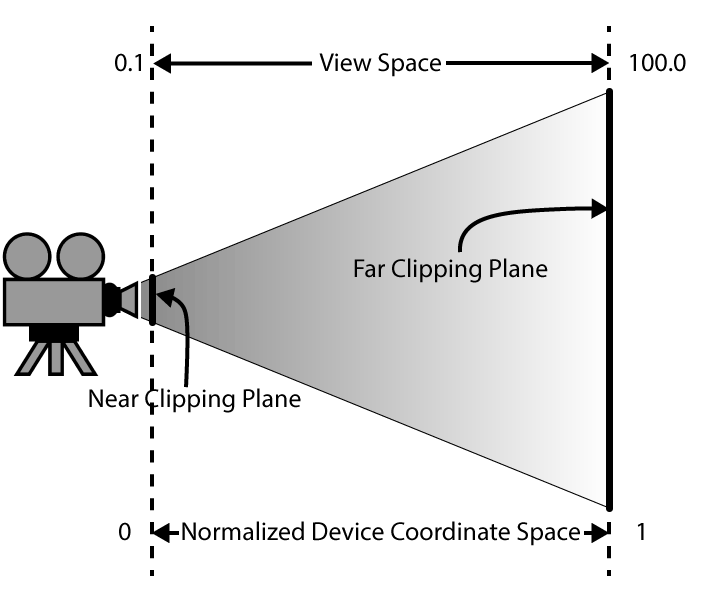
The depth buffer stores the depth of the current pixel in normalized device coordinate space (NDC)
Similar to the Render Target Views (RTV) that were created for the swap-chain buffers in the previous lesson, the depth buffer requires a Depth-Stencil View (DSV). The DSV is stored in a descriptor heap. A descriptor heap is an array of descriptors (resource views). A descriptor heap is required even if only a single DSV is needed.
|
1 2 3 4 5 6 |
// Create the descriptor heap for the depth-stencil view. D3D12_DESCRIPTOR_HEAP_DESC dsvHeapDesc = {}; dsvHeapDesc.NumDescriptors = 1; dsvHeapDesc.Type = D3D12_DESCRIPTOR_HEAP_TYPE_DSV; dsvHeapDesc.Flags = D3D12_DESCRIPTOR_HEAP_FLAG_NONE; ThrowIfFailed(device->CreateDescriptorHeap(&dsvHeapDesc, IID_PPV_ARGS(&m_DSVHeap))); |
The D3D12_DESCRIPTOR_HEAP_DESC structure is used to describe the descriptor heap.
The D3D12_DESCRIPTOR_HEAP_DESC structure has the following syntax:
|
1 2 3 4 5 6 |
typedef struct D3D12_DESCRIPTOR_HEAP_DESC { D3D12_DESCRIPTOR_HEAP_TYPE Type; UINT NumDescriptors; D3D12_DESCRIPTOR_HEAP_FLAGS Flags; UINT NodeMask; } D3D12_DESCRIPTOR_HEAP_DESC; |
And has the following members:
D3D12_DESCRIPTOR_HEAP_TYPE Type: AD3D12_DESCRIPTOR_HEAP_TYPE-typed value that specifies the types of descriptors in the heap.UINT NumDescriptors: The number of descriptors in the heap. In this case, only one descriptor is needed.D3D12_DESCRIPTOR_HEAP_FLAGS Flags: A combination ofD3D12_DESCRIPTOR_HEAP_FLAGS-typed values that are combined by using a bitwise OR operation. The resulting value specifies options for the heap. The following options are available for descriptor heaps:D3D12_DESCRIPTOR_HEAP_FLAG_NONE: Indicates default usage of a heap.D3D12_DESCRIPTOR_HEAP_FLAG_SHADER_VISIBLE: The flagD3D12_DESCRIPTOR_HEAP_FLAG_SHADER_VISIBLEcan optionally be set on a descriptor heap to indicate it can be be bound on a command list for reference by shaders. Descriptor heaps created without this flag allow applications the option to stage descriptors in CPU memory before copying them to a shader visible descriptor heap, as a convenience. But it is also fine for applications to directly create descriptors into shader visible descriptor heaps with no requirement to stage anything on the CPU.
This flag only applies to CBV, SRV, UAV and samplers. It does not apply to other descriptor heap types (RTV, DSV) since shaders do not directly reference the other types.
UINT NodeMask: For single-adapter operation, set this to zero. If there are multiple adapter nodes, set a bit to identify the node (one of the device’s physical adapters) to which the descriptor heap applies. Each bit in the mask corresponds to a single node. Only one bit must be set.
The descriptor heap is created on line 146 using the ID3D12Device::CreateDescriptorHeap method.
Load the Shaders
If the Visual Studio project is configured correctly, then any HLSL shader file (any file with the .hlsl extension) that is added to the project will automatically be compiled into a shader object file that can be loaded by the application at runtime. By default, shaders are compiled into a Compiled Shader Object file (.cso) with the same name as the original .hlsl file. For example, VertexShader.hlsl will be compiled as VertexShader.cso. The CSO file can be loaded directly into a binary object using the D3DReadFileToBlob function.
D3DReadFileToBlob function, or any function in the D3DCompiler API, do not forget to include the d3dcompiler.h header file in your source and link against the D3Dcompiler_47.lib library and copy the D3dcompiler_47.dll file to the same folder as the binary executable when distributing your project.A redistributable version of the D3dcompiler_47.dll file can be found in the Windows 10 SDK installation folder at
For more information, refer to the MSDN blog post at: https://blogs.msdn.microsoft.com/chuckw/2012/05/07/hlsl-fxc-and-d3dcompile/
|
1 2 3 4 5 6 7 |
// Load the vertex shader. ComPtr<ID3DBlob> vertexShaderBlob; ThrowIfFailed(D3DReadFileToBlob(L"VertexShader.cso", &vertexShaderBlob)); // Load the pixel shader. ComPtr<ID3DBlob> pixelShaderBlob; ThrowIfFailed(D3DReadFileToBlob(L"PixelShader.cso", &pixelShaderBlob)); |
By default, the shader compiler (FXC.exe) will generate the .cso file in the same directory as the output directory for the project. If the current working directory for the currently running process is configured to be the same folder where the executable is located, then it should be sufficient to load the shader from the .cso file using the path relative to the executable.
The D3DReadFileToBlob function takes the path to the file (as a wide character string) to load and returns a pointer to a ID3DBlob object that stores the compiled shader in binary format.
D3DCompileFromFile function to compile your HLSL shaders at runtime instead of using the FXC compiler integrated in Visual Studio.The compiled shader objects in binary form are used later to create the graphics pipeline state object. Before the graphics pipeline state object can be created, the input layout for the vertex shader is defined.
Input Layout
The Input Layout describes the layout of the vertex buffers that are bound to to the Input Assembler stage of the rendering pipeline. For example, the vertex attributes that are passed to the vertex shader could look like this in the HLSL shader file:
|
1 2 3 4 5 |
struct VertexPosColor { float3 Position : POSITION; float3 Color : COLOR; }; |
These two attributes can be described in words as:
- The first parameter is a 3-component floating-point value bound to the
POSITIONsemantic. - The second parameter is a 3-component floating-point value bound to the
COLORsemantic.
As described previously, vertex attributes can be passed to the vertex shader in either packed or interleaved buffer format. There is no way to specify whether the vertex attributes are passed as packed or interleaved formats in HLSL. The only way to specify the buffer format is by using the Input Layout.
The Input Layout is specified using an array of D3D12_INPUT_ELEMENT_DESC structures. This structure has the following syntax [14]:
|
1 2 3 4 5 6 7 8 9 |
typedef struct D3D12_INPUT_ELEMENT_DESC { LPCSTR SemanticName; UINT SemanticIndex; DXGI_FORMAT Format; UINT InputSlot; UINT AlignedByteOffset; D3D12_INPUT_CLASSIFICATION InputSlotClass; UINT InstanceDataStepRate; } D3D12_INPUT_ELEMENT_DESC; |
And has the following members:
LPCSTR SemanticName: The HLSL semantic associated with this element in a shader input-signature.UINT SemanticIndex: The semantic index for the element. A semantic index modifies a semantic, with an integer index number. A semantic index is only needed in a case where there is more than one element with the same semantic. For example, a 4×4 matrix would have four components each with the semantic name matrix, however each of the four component would have different semantic indices (0, 1, 2, and 3).DXGI_FORMAT Format: ADXGI_FORMAT-typed value that specifies the format of the element data.UINT InputSlot: An integer value that identifies the input-assembler. For more info, see Input Slots. Valid values are between 0 and 15.UINT AlignedByteOffset: Offset, in bytes, between each element. UseD3D12_APPEND_ALIGNED_ELEMENT(0xffffffff) for convenience to define the current element directly after the previous one, including any packing if necessary.D3D12_INPUT_CLASSIFICATION InputSlotClass: A value that identifies the input data class for a single input slot. Valid values for InputSlotClass are:D3D12_INPUT_CLASSIFICATION_PER_VERTEX_DATA: Input data is per-vertex data.D3D12_INPUT_CLASSIFICATION_PER_INSTANCE_DATA: Input data is per-instance data.
UINT InstanceDataStepRate: The number of instances to draw using the same per-instance data before advancing in the buffer by one element. This value must be 0 for an element that contains per-vertex data (the slot class is set toD3D12_INPUT_CLASSIFICATION_PER_VERTEX_DATA).
The Input Layout for the simple vertex shader for this lesson is:
|
1 2 3 4 5 |
// Create the vertex input layout D3D12_INPUT_ELEMENT_DESC inputLayout[] = { { "POSITION", 0, DXGI_FORMAT_R32G32B32_FLOAT, 0, D3D12_APPEND_ALIGNED_ELEMENT, D3D12_INPUT_CLASSIFICATION_PER_VERTEX_DATA, 0 }, { "COLOR", 0, DXGI_FORMAT_R32G32B32_FLOAT, 0, D3D12_APPEND_ALIGNED_ELEMENT, D3D12_INPUT_CLASSIFICATION_PER_VERTEX_DATA, 0 }, }; |
The first per-vertex attribute is bound to the POSITION semantic at index 0 in the HLSL shader. The data contains a 3-component floating-point format (DXGI_FORMAT_R32G32B32_FLOAT) and the buffer is bound to input slot 0 of the Input Assembler. The offset to the first element in the buffer is 0 and the elements are automatically aligned using the D3D12_APPEND_ALIGNED_ELEMENT macro.
The second per-vertex attribute is bound to the COLOR semantic at index 0 in the HLSL shader. The data contains a 3-component floating-point format (DXGI_FORMAT_R32G32B32_FLOAT) and is also bound to input slot 0 of the Input Assembler. The offset to the first element in the buffer is 0 (preceding the previous element in the same input slot) and elements in the buffer are automatically aligned after the previous element in the buffer using the D3D12_APPEND_ALIGNED_ELEMENT macro.
It is possible to avoid the use of Input Layouts by storing the vertex buffer data in one or more
StructuredBuffers in HLSL. Try changing the vertex shader in this demo to read from a StructuredBuffer in HLSL instead of using a vertex buffer.Root Signature
The root signature describes the parameters that are passed to the programmable stages of the rendering (or compute) pipeline. Before the pipeline state object (PSO) can be created, the root signature needs to be defined. The various types of root signature parameters were described in the previous section titled Root Signature Parameters. In this section, the source code to configure a simple root signature is shown.
For this simple demo, the root signature contains a single 32-bit constant parameter. More complex root signatures using inline descriptors and descriptor tables are described in later lessons.
Before creating the root signature, the highest supported version of the root signature is queried. Root signature version 1.1 should be preferred because it allows for driver level optimizations to be made. Root signature version 1.0 allowed both descriptors and the data pointed to by the descriptor to be changed after being recorded to a command list but before being executed on the command queue (the descriptors and data are volatile). Version 1.1 assumes that descriptors set on the root signature are static (that the descriptors won’t change after they have been recorded on the command list). The D3D12_DESCRIPTOR_RANGE_FLAG_DESCRIPTORS_VOLATILE flag must be specified on the descriptor range in the root signature if descriptors are updated after they have been recorded on the command list. The default behaviour of root signature version 1.1 allows the driver to make optimizations (for example, copy the descriptors or data to the GPU before the command list is even executed) if it will improve performance.
|
1 2 3 4 5 6 7 |
// Create a root signature. D3D12_FEATURE_DATA_ROOT_SIGNATURE featureData = {}; featureData.HighestVersion = D3D_ROOT_SIGNATURE_VERSION_1_1; if (FAILED(device->CheckFeatureSupport(D3D12_FEATURE_ROOT_SIGNATURE, &featureData, sizeof(featureData)))) { featureData.HighestVersion = D3D_ROOT_SIGNATURE_VERSION_1_0; } |
Root signature version 1.1 is preferred but the driver supported version on the end-user’s computer must be verified using the ID3D12Device::CheckFeatureSupport method. If the check fails, the root signature version will fall-back to the root signature version 1.0.
Next, the root signature flags are defined.
|
1 2 3 4 5 6 7 |
// Allow input layout and deny unnecessary access to certain pipeline stages. D3D12_ROOT_SIGNATURE_FLAGS rootSignatureFlags = D3D12_ROOT_SIGNATURE_FLAG_ALLOW_INPUT_ASSEMBLER_INPUT_LAYOUT | D3D12_ROOT_SIGNATURE_FLAG_DENY_HULL_SHADER_ROOT_ACCESS | D3D12_ROOT_SIGNATURE_FLAG_DENY_DOMAIN_SHADER_ROOT_ACCESS | D3D12_ROOT_SIGNATURE_FLAG_DENY_GEOMETRY_SHADER_ROOT_ACCESS | D3D12_ROOT_SIGNATURE_FLAG_DENY_PIXEL_SHADER_ROOT_ACCESS; |
The supported root signature flags are [16]:
D3D12_ROOT_SIGNATURE_FLAG_NONE: The default behaviour.D3D12_ROOT_SIGNATURE_FLAG_ALLOW_INPUT_ASSEMBLER_INPUT_LAYOUT: The app is opting in to using the Input Assembler (requiring an input layout that defines a set of vertex buffer bindings). Omitting this flag can result in one root argument space being saved on some hardware. Omit this flag if the Input Assembler is not required, though the optimization is minor.D3D12_ROOT_SIGNATURE_FLAG_DENY_VERTEX_SHADER_ROOT_ACCESS: Denies the vertex shader access to the root signature.D3D12_ROOT_SIGNATURE_FLAG_DENY_HULL_SHADER_ROOT_ACCESS: Denies the hull shader access to the root signature.D3D12_ROOT_SIGNATURE_FLAG_DENY_DOMAIN_SHADER_ROOT_ACCESS: Denies the domain shader access to the root signature.D3D12_ROOT_SIGNATURE_FLAG_DENY_GEOMETRY_SHADER_ROOT_ACCESS: Denies the geometry shader access to the root signature.D3D12_ROOT_SIGNATURE_FLAG_DENY_PIXEL_SHADER_ROOT_ACCESS: Denies the pixel shader access to the root signature.D3D12_ROOT_SIGNATURE_FLAG_ALLOW_STREAM_OUTPUT: The root signature allows stream output. This flag can be specified for root signatures authored in HLSL, similar to how the other flags are specified.ID3D12Device::CreateGraphicsPipelineStatewill fail if the geometry shader contains stream output but the root signature does not have this flag set. Omit this flag if stream output is not required.
For this simple demo, only the vertex shader stage requires root signature access. Denying access to shader stages that do not require root signature access is a minor optimization on some hardware.
The root signature consists of a single 32-bit constant parameter.
|
1 2 3 |
// A single 32-bit constant root parameter that is used by the vertex shader. CD3DX12_ROOT_PARAMETER1 rootParameters[1]; rootParameters[0].InitAsConstants(sizeof(XMMATRIX) / 4, 0, 0, D3D12_SHADER_VISIBILITY_VERTEX); |
The CD3DX12_ROOT_PARAMETER1 is a helper structure from the d3dx12.h header file that allows for easy initialization of a D3D12_ROOT_PARAMETER1 structure. The InitAsConstants method takes the following parameters:
UINT num32BitValues: The number of 32-bit constants. In this case, theXMMATRIXstructure contains 16 32-bit floating-point values.UINT shaderRegister: The shader register to bind to. This parameter is bound tob0in the vertex shader.UINT registerSpace: The register space to bind to. Since no shader register space was specified in the vertex shader, this defaults tospace0.D3D12_SHADER_VISIBILITY visibility: Specifies the shader stages that are allowed to access the contents at that root signature slot. In this case, the visibility of the 32-bit constants is restricted to the vertex shader stage.
After describing the parameters (and samplers) that are used by the root signature, the next step is to create the the root signature description.
|
1 2 |
CD3DX12_VERSIONED_ROOT_SIGNATURE_DESC rootSignatureDescription; rootSignatureDescription.Init_1_1(_countof(rootParameters), rootParameters, 0, nullptr, rootSignatureFlags); |
The CD3DX12_VERSIONED_ROOT_SIGNATURE_DESC is a helper structure from the d3dx12.h header file that allows for easy initialization of a D3D12_VERSIONED_ROOT_SIGNATURE_DESC structure.
The Init_1_1 method takes the following parameters:
UINT numParameters: The number of root parameters in the root signature. In this case, there is only a single root parameter.D3D12_ROOT_PARAMETER1* _pParameters: An array of numParameters root parameters. The array of root parameters contains only a single 32-bit root constant parameter.UINT numStaticSamplers: The number of static samplers in the root signature.D3D12_STATIC_SAMPLER_DESC* _pStaticSamplers: An array of numStaticSamplers static samplers.D3D12_ROOT_SIGNATURE_FLAGS flags: Flags that determine the root signature visibility to the various shader stages.
The final step for creating the root signature is to serialize the root signature description into a binary object that can be used to create the actual root signature.
|
1 2 3 4 5 6 7 8 |
// Serialize the root signature. ComPtr<ID3DBlob> rootSignatureBlob; ComPtr<ID3DBlob> errorBlob; ThrowIfFailed(D3DX12SerializeVersionedRootSignature(&rootSignatureDescription, featureData.HighestVersion, &rootSignatureBlob, &errorBlob)); // Create the root signature. ThrowIfFailed(device->CreateRootSignature(0, rootSignatureBlob->GetBufferPointer(), rootSignatureBlob->GetBufferSize(), IID_PPV_ARGS(&m_RootSignature))); |
On line 188 the root signature is serialized using the D3DX12SerializeVersionedRootSignature function. This function is part of the d3dx12.h header file and provides a method to serialize any root signature version using a single code path. This function will rewrite the root signature description for hardware that only supports version 1.0 even if the application developer passes a version 1.1 root signature (as is done in this example).
Similar to pre-compiling HLSL shaders, it is also possible to pre-compile root signatures. Pre-compiling root signatures has the benefit of shorter load times when there are many shader combinations each requiring a unique root signature. For this demo, the root signature is serialized at runtime but for production code, it is advisable to serialize the root signatures during compilation and save them to disc and load the pre-serialized root signature at runtime. It is also possible to define the root signatures directly in HLSL code and read the serialized root signature directly from the compiled shader object. Specifying root signatures in HLSL is beyond the scope of this article, but anyone that is interested is encouraged to read Specifying Root Signatures in HLSL.
On line 191 the actual root signature object is created from the serialized root signature using the ID3D12Device::CreateRootSignature method.
Pipeline State Object
The next step is to create the Pipeline State Object (PSO). The PSO is described using a Pipeline State Stream structure. The Pipeline State Stream structure contains a set of stream tokens that describe how to configure the PSO. An example of a stream token for a Pipeline State Stream object is the Vertex Shader (VS), Geometry Shader (GS) or Pixel Shader (PS). You only need to specify stream tokens that will override the default values of that token. For example, if tessellation shaders (Hull and Domain Shaders) are not required for the PSO, then they do not need to be defined in the Pipeline State Stream structure.
For this simple demo, only the following stream tokens need to be defined in the Pipeline State Stream structure:
- Root Signature
- Input Layout
- Primitive Topology
- Vertex Shader
- Pixel Shader
- Depth-Stencil Format
- Render Target Format(s)
The order that the stream tokens appear in the Pipeline State Stream structure are not important. When the Pipeline State Stream is parsed, the type of each token is used to determine how the PSO is created.
The PipelineStateStream structure defines the tokens that are used to define the PSO.
|
1 2 3 4 5 6 7 8 9 10 |
struct PipelineStateStream { CD3DX12_PIPELINE_STATE_STREAM_ROOT_SIGNATURE pRootSignature; CD3DX12_PIPELINE_STATE_STREAM_INPUT_LAYOUT InputLayout; CD3DX12_PIPELINE_STATE_STREAM_PRIMITIVE_TOPOLOGY PrimitiveTopologyType; CD3DX12_PIPELINE_STATE_STREAM_VS VS; CD3DX12_PIPELINE_STATE_STREAM_PS PS; CD3DX12_PIPELINE_STATE_STREAM_DEPTH_STENCIL_FORMAT DSVFormat; CD3DX12_PIPELINE_STATE_STREAM_RENDER_TARGET_FORMATS RTVFormats; } pipelineStateStream; |
The PipelineStateStream structure is a user-defined structure that describes the stream tokens required to configure the PSO. The d3dx12.h header file defines a few helper classes that can be used to define the pipeline stream structure.
d3dx12.h header file available here:https://github.com/Microsoft/DirectX-Graphics-Samples/tree/master/Libraries/D3DX12
Currently the following helper classes are available in the d3dx12.h header file for defining the PipelineStateStream structure:
CD3DX12_PIPELINE_STATE_STREAM_FLAGS: Wrapper for aD3D12_PIPELINE_STATE_FLAGSenumeration.CD3DX12_PIPELINE_STATE_STREAM_NODE_MASK: Describes the pipeline state node mask as a UINT, which is used to identify the nodes (physical adapters of the device) that the PSO applies to in Multi-Adapter scenarios; each bit in the mask corresponds to a single node. For single-adapter scenarios, set this value to 0.CD3DX12_PIPELINE_STATE_STREAM_ROOT_SIGNATURE: Wrapper for a pointer to aID3D12RootSignature.CD3DX12_PIPELINE_STATE_STREAM_INPUT_LAYOUT: Wrapper for aD3D12_INPUT_LAYOUT_DESC. Specifies the input layout for the input assembly stage.CD3DX12_PIPELINE_STATE_STREAM_IB_STRIP_CUT_VALUE: Wrapper for aD3D12_INDEX_BUFFER_STRIP_CUT_VALUEenumeration. Used to specify the index buffer value to split line strips or triangle strips.CD3DX12_PIPELINE_STATE_STREAM_PRIMITIVE_TOPOLOGY: Wrapper for aD3D12_PRIMITIVE_TOPOLOGY_TYPEenumeration. Used to specify the primitive topology type (point, line, triangle or patch). Do not mistake this with theD3D_PRIMITIVE_TOPOLOGYenumeration!CD3DX12_PIPELINE_STATE_STREAM_VS: Wrapper for aD3D12_SHADER_BYTECODEstructure. Used to specify the compiled Vertex Shader (VS).CD3DX12_PIPELINE_STATE_STREAM_GS: Wrapper for aD3D12_SHADER_BYTECODEstructure. Used to specify the compiled Geometry Shader (GS).CD3DX12_PIPELINE_STATE_STREAM_STREAM_OUTPUT: Wrapper for aD3D12_STREAM_OUTPUT_DESCstructure. Describes the streaming output buffers for the Stream Output (SO) stage.CD3DX12_PIPELINE_STATE_STREAM_HS: Wrapper for aD3D12_SHADER_BYTECODEstructure. Used to specify the compiled Hull Shader (HS).CD3DX12_PIPELINE_STATE_STREAM_DS: Wrapper for aD3D12_SHADER_BYTECODEstructure. Used to specify the compiled Domain Shader (DS).CD3DX12_PIPELINE_STATE_STREAM_PS: Wrapper for aD3D12_SHADER_BYTECODEstructure. Used to specify the compiled Pixel Shader (PS).CD3DX12_PIPELINE_STATE_STREAM_CS: Wrapper for aD3D12_SHADER_BYTECODEstructure. Used to specify the compiled Compute Shader (CS).CD3DX12_PIPELINE_STATE_STREAM_BLEND_DESC: Wraper for aD3D12_BLEND_DESCstructure. Used to describes the blend state.CD3DX12_PIPELINE_STATE_STREAM_DEPTH_STENCILWrapper for aD3D12_DEPTH_STENCIL_DESCstructure. Used to describe the depth-stencil state.CD3DX12_PIPELINE_STATE_STREAM_DEPTH_STENCIL1: Wrapper for aD3D12_DEPTH_STENCIL_DESC1structure. Used to describe the depth-stencil state. This version adds the ability to enable depth-bounds testing.CD3DX12_PIPELINE_STATE_STREAM_DEPTH_STENCIL_FORMAT: Wrapper for aDXGI_FORMATenumeration. Describes the format of the depth-stencil buffer.CD3DX12_PIPELINE_STATE_STREAM_RASTERIZER: Wrapper for theD3D12_RASTERIZER_DESCstructure. Used to describe the Rasterizer State (RS)CD3DX12_PIPELINE_STATE_STREAM_RENDER_TARGET_FORMATS: Wrapper for theD3D12_RT_FORMAT_ARRAYstructure which is a wrapper for an array of render target formats.CD3DX12_PIPELINE_STATE_STREAM_SAMPLE_DESC: Wrapper for theDXGI_SAMPLE_DESCstructure. Used to describe the multi-sampling. The render targets must also be created with multisampling enabled.CD3DX12_PIPELINE_STATE_STREAM_SAMPLE_MASK: AUINTthat describes the sample mask for the blend state.CD3DX12_PIPELINE_STATE_STREAM_CACHED_PSO: A wrapper for theD3D12_CACHED_PIPELINE_STATEstructure. The cached PSO can be used to quickly load the PSO after it has been created. Using cached PSO’s can improve load times.CD3DX12_PIPELINE_STATE_STREAM_VIEW_INSTANCING: A wrapper for aD3D12_VIEW_INSTANCING_DESCstructure. Allows shaders to render to multiple views with a single draw call. Useful for stereo vision or cubemap generation.
The helper classes listed are the ones that are available at the time this article was written but more could become available at any time. For example, the DirectX 12 Raytracing API was recently announced (Announcing Microsoft DirectX Raytracing!) which will no doubt introduce more Pipeline State Stream Tokens to the rendering pipeline.
Before the Pipeline State Object can be created, the number of render targets and the render target formats are defined.
|
1 2 3 |
D3D12_RT_FORMAT_ARRAY rtvFormats = {}; rtvFormats.NumRenderTargets = 1; rtvFormats.RTFormats[0] = DXGI_FORMAT_R8G8B8A8_UNORM; |
The D3D12_RT_FORMAT_ARRAY structure is used to describe the number of render targtes and the formats of those render targets.
The PSO can now be described.
|
1 2 3 4 5 6 7 |
pipelineStateStream.pRootSignature = m_RootSignature.Get(); pipelineStateStream.InputLayout = { inputLayout, _countof(inputLayout) }; pipelineStateStream.PrimitiveTopologyType = D3D12_PRIMITIVE_TOPOLOGY_TYPE_TRIANGLE; pipelineStateStream.VS = CD3DX12_SHADER_BYTECODE(vertexShaderBlob.Get()); pipelineStateStream.PS = CD3DX12_SHADER_BYTECODE(pixelShaderBlob.Get()); pipelineStateStream.DSVFormat = DXGI_FORMAT_D32_FLOAT; pipelineStateStream.RTVFormats = rtvFormats; |
The properties of the PSO are now being filled in with the various objects that have already been described earlier. The pipelineStateStream structure is now complete and the actual Pipeline State Object can be created.
|
1 2 3 4 |
D3D12_PIPELINE_STATE_STREAM_DESC pipelineStateStreamDesc = { sizeof(PipelineStateStream), &pipelineStateStream }; ThrowIfFailed(device->CreatePipelineState(&pipelineStateStreamDesc, IID_PPV_ARGS(&m_PipelineState))); |
To create the pipeline state object, the PipelStateStream object must be wrapped in a D3D12_PIPELINE_STATE_STREAM_DESC structure. This is in-turn passed to the ID3D12Device2::CreatePipelineState method to create the final ID3D12PipelineState object which is what is required for rendering.
Before leaving the LoadContent method, the command list must be executed on the command queue to ensure that the index and vertex buffers are uploaded to the GPU resources before rendering.
|
1 2 3 4 |
auto fenceValue = commandQueue->ExecuteCommandList(commandList); commandQueue->WaitForFenceValue(fenceValue); m_ContentLoaded = true; |
On line 222 the command list is executed on the command queue. The CommandQueue::ExecuteCommandList returns the fence value that is used to indicate when the command list is finished executing on the command queue. On line 223 the CPU thread is stalled until the fence value has been reached. At this point, it is safe to render the frame.
The m_ContentLoaded flag is set to true which indicates that other functions that rely on the content being loaded can run.
Depth Buffer
The depth buffer has been mentioned earlier in this article, but the creation of the depth buffer has not yet been described. The creation (or resizing) of the depth buffer has a dependency on the depth-stencil descriptor heap that was created on lines 142-146. Once the descriptor heap has been created, it is now safe to create the depth buffer.
|
1 2 3 4 5 |
// Resize/Create the depth buffer. ResizeDepthBuffer(GetClientWidth(), GetClientHeight()); return true; } |
The ResizeDepthBuffer method is described next. It will either create the depth buffer for the first time, or it will create a new depth buffer that matches the size of the client area and replace the previous depth buffer.
Tutorial2::ResizeDepthBuffer
The ResizeDepthBuffer method is used to create (or resize) the depth buffer. It is important to make sure that there are no command lists that are currently referencing the depth buffer before the previous depth buffer is released. To ensure that the depth buffer is not being referenced by any command lists being executed on the command queue, each command queue owned by the application is flushed.
|
1 2 3 4 5 6 7 8 9 10 11 |
void Tutorial2::ResizeDepthBuffer(int width, int height) { if (m_ContentLoaded) { // Flush any GPU commands that might be referencing the depth buffer. Application::Get().Flush(); width = std::max(1, width); height = std::max(1, height); auto device = Application::Get().GetDevice(); |
The ResizeDepthBuffer function takes the width and height of the back buffer as arguments. To ensure that the depth buffer is resized (due to a resize event generated by the Window) before the depth-stencil descriptor heap is created, the m_ContentLoaded flag is checked. This flag is set at the end of the LoadContent method so it will only be true after the descriptor heap has been created.
The Application::Flush method is used to ensure that there are no command lists that could be referencing the current depth buffer are “in-flight” on the command queue.
If the window is minimized, it is possible that either the width or the height of the client area of the window becomes 0. Creating a resource with a 0 size is an error so to prevent the buffer from being created with a 0 size, the width and height are clamped to a size of at least 1 in both dimensions.
The Application class has ownership of the DirectX 12 device. On line 243 the device is retrieved from the Application class.
|
1 2 3 4 5 6 7 8 9 10 11 12 13 14 15 |
// Resize screen dependent resources. // Create a depth buffer. D3D12_CLEAR_VALUE optimizedClearValue = {}; optimizedClearValue.Format = DXGI_FORMAT_D32_FLOAT; optimizedClearValue.DepthStencil = { 1.0f, 0 }; ThrowIfFailed(device->CreateCommittedResource( &CD3DX12_HEAP_PROPERTIES(D3D12_HEAP_TYPE_DEFAULT), D3D12_HEAP_FLAG_NONE, &CD3DX12_RESOURCE_DESC::Tex2D(DXGI_FORMAT_D32_FLOAT, width, height, 1, 0, 1, 0, D3D12_RESOURCE_FLAG_ALLOW_DEPTH_STENCIL), D3D12_RESOURCE_STATE_DEPTH_WRITE, &optimizedClearValue, IID_PPV_ARGS(&m_DepthBuffer) )); |
The ID3D12Device::CreateCommittedResource method was previously described in the Tutorial2::UpdateBufferResource method. The only difference in this case is the ID3D12Device::CreateCommittedResource method is being used to create a texture instead of a buffer.
The D3D12_CLEAR_VALUE structure is used to describe the optimized clear color for the depth-stencil buffer. This structure is used for both depth-stencil and color textures.
The CD3DX12_RESOURCE_DESC::Tex2D method is a helper function used to create a D3D12_RESOURCE_DESC structure. The CD3DX12_RESOURCE_DESC::Tex2D method takes the following arguments [17]:
DXGI_FORMAT format: The format of the texture.UINT64 width: Width of the texture in pixels.UINT height: The height of the texture in pixels.UINT16 arraySize: The number of texture elements. For a single texture this value must be 1.UINT16 mipLevels: The number of mip levels. A value of 0 will cause the number of mip levels to be calculated automatically based on the maximum of either the width or the height of the texture.UINT sampleCount: The number of milti-samples per pixel. The default value forsampleCountis 1.UINT sampleQuality: The quality level for multi-sampling. The default value forsampleQualityis 0.D3D12_RESOURCE_FLAGS flags: A bitwise combination ofD3D12_RESOURCE_FLAGSenumeration values. Since this is a depth-stencil buffer, theD3D12_RESOURCE_FLAG_ALLOW_DEPTH_STENCILflag must be specified.D3D12_TEXTURE_LAYOUT layout: Specifies the texture layout options. The default value isD3D12_TEXTURE_LAYOUT_UNKNOWNwhich allows the driver to choose the most optimized layout based on the properties of the texture.UINT64 alignment: Specify the alignment of the texture. This can be 4KB, 64KB, or 4MB. The default value of 0 can be used to allow the API to automatically choose the alignment based on the texture properties. Multi-sample textures will be created with 4MB alignment and 64KB for single-sample textures. Smaller alignments are used if the texture is sufficiently small (if the number of 4KB tiles is less than 16 for the highest (largest) mip level of the texture).
Textures will be revisited in the following lessons.
The depth-stencil view for the depth buffer is created next.
|
1 2 3 4 5 6 7 8 9 10 11 |
// Update the depth-stencil view. D3D12_DEPTH_STENCIL_VIEW_DESC dsv = {}; dsv.Format = DXGI_FORMAT_D32_FLOAT; dsv.ViewDimension = D3D12_DSV_DIMENSION_TEXTURE2D; dsv.Texture2D.MipSlice = 0; dsv.Flags = D3D12_DSV_FLAG_NONE; device->CreateDepthStencilView(m_DepthBuffer.Get(), &dsv, m_DSVHeap->GetCPUDescriptorHandleForHeapStart()); } } |
The D3D12_DEPTH_STENCIL_VIEW_DESC structure is used to describe a depth-stencil resource. The D3D12_DEPTH_STENCIL_VIEW_DESC has the following syntax [18]:
|
1 2 3 4 5 6 7 8 9 10 11 12 13 |
typedef struct D3D12_DEPTH_STENCIL_VIEW_DESC { DXGI_FORMAT Format; D3D12_DSV_DIMENSION ViewDimension; D3D12_DSV_FLAGS Flags; union { D3D12_TEX1D_DSV Texture1D; D3D12_TEX1D_ARRAY_DSV Texture1DArray; D3D12_TEX2D_DSV Texture2D; D3D12_TEX2D_ARRAY_DSV Texture2DArray; D3D12_TEX2DMS_DSV Texture2DMS; D3D12_TEX2DMS_ARRAY_DSV Texture2DMSArray; }; } D3D12_DEPTH_STENCIL_VIEW_DESC; |
And has the following members:
DXGI_FORMAT Format: The depth-stencil format. This should be the same format that was used to create the texture but it could be a different format if the view is for a Shader Resource.D3D12_DSV_DIMENSION ViewDimension: One value from theD3D12_DSV_DIMENSIONenumeration. In this case, it is a 2D texture.D3D12_DSV_FLAGS Flags: A combination ofD3D12_DSV_FLAGSenumeration constants that are combined by using a bitwise OR operation. The resulting value specifies whether the texture is read only. Pass 0 to specify that it isn’t read only; otherwise, pass one or more of the members of theD3D12_DSV_FLAGSenumerated type.- One of the following is specified depending on the value of the
ViewDimensionmember:D3D12_TEX1D_DSV Texture1D: AD3D12_TEX1D_DSVstructure that specifies a 1D texture subresource.D3D12_TEX1D_ARRAY_DSV Texture1DArray: AD3D12_TEX1D_ARRAY_DSVstructure that specifies an array of 1D texture subresources.D3D12_TEX2D_DSV Texture2D: AD3D12_TEX2D_DSVstructure that specifies a 2D texture subresource.D3D12_TEX2D_ARRAY_DSV Texture2DArray: AD3D12_TEX2D_ARRAY_DSVstructure that specifies an array of 2D texture subresources.D3D12_TEX2DMS_DSV Texture2DMS: AD3D12_TEX2DMS_DSVstructure that specifies a multisampled 2D texture.D3D12_TEX2DMS_ARRAY_DSV Texture2DMSArray: AD3D12_TEX2DMS_ARRAY_DSVstructure that specifies an array of multisampled 2D textures.
On line 268, the depth-stencil view is created using the ID3D12Device::CreateDepthStencilView method. The ID3D12Device::CreateDepthStencilView method has the following syntax [19]:
|
1 2 3 4 5 |
void CreateDepthStencilView( [in, optional] ID3D12Resource *pResource, [in, optional] const D3D12_DEPTH_STENCIL_VIEW_DESC *pDesc, [in] D3D12_CPU_DESCRIPTOR_HANDLE DestDescriptor ); |
And has the following parameters:
ID3D12Resource *pResource: A pointer to theID3D12Resourceobject that represents the depth stencil buffer.
At least one ofpResourceorpDescmust be provided. A nullpResourceis used to initialize a null descriptor, which guarantees D3D11-like null binding behavior (reading 0s, writes are discarded), but must have a validpDescin order to determine the descriptor type.D3D12_DEPTH_STENCIL_VIEW_DESC *pDesc: A pointer to aD3D12_DEPTH_STENCIL_VIEW_DESCstructure that describes the depth-stencil view.
A nullpDescis used to initialize a default descriptor, if possible. This behavior is identical to the D3D11 null descriptor behavior, where defaults are filled in. This behavior inherits the resource format and dimension (if not typeless) and DSVs target the first mip and all array slices. Not all resources support null descriptor initialization.D3D12_CPU_DESCRIPTOR_HANDLE DestDescriptor: Describes the CPU descriptor handle that represents the start of the heap that holds the depth-stencil view.
Tutorial2::OnResize
The OnResize method is invoked by the Window class whenever the client area of window is resized. This happens if either the edge of the window is dragged with the mouse, or the fullscreen state of the window is toggled. This method is very simple and only needs to handle resizing of the m_Viewport member variable. Resizing of the swap-chain back buffers is automatically handled by the Window class itself.
|
1 2 3 4 5 6 7 8 9 10 11 12 |
void Tutorial2::OnResize(ResizeEventArgs& e) { if (e.Width != GetClientWidth() || e.Height != GetClientHeight()) { super::OnResize(e); m_Viewport = CD3DX12_VIEWPORT(0.0f, 0.0f, static_cast<float>(e.Width), static_cast<float>(e.Height)); ResizeDepthBuffer(e.Width, e.Height); } } |
The m_Viewport member variable must match the dimensions of the rederable area of the render target. The CD3DX12_VIEWPORT structure provides a convenient method to initialize the viewport.
The ResizeDepthBuffer method was described in the previous section. That method ensures that the depth buffer is resized to the same dimensions as the client area of the window.
Tutorial2::OnUpdate
The OnUpdate method is called before the screen is rendered. This method is used to update the model, view and projection matrices. The cube mesh is rotated 90° per second and the field of view of the camera is also adjusted using the scroll wheel of the mouse. When the field of view of the camera changes, the projection matrix needs to be recomputed.
The frame-rate is also computed and printed to the debug output in Visual Studio.
|
1 2 3 4 5 6 7 8 9 10 11 12 13 14 15 16 17 18 19 20 21 |
void Tutorial2::OnUpdate(UpdateEventArgs& e) { static uint64_t frameCount = 0; static double totalTime = 0.0; super::OnUpdate(e); totalTime += e.ElapsedTime; frameCount++; if (totalTime > 1.0) { double fps = frameCount / totalTime; char buffer[512]; sprintf_s(buffer, "FPS: %f\n", fps); OutputDebugStringA(buffer); frameCount = 0; totalTime = 0.0; } |
In the first part of the OnUpdate method the frame-rate is computed and output to the debug output in Visual Studio. The UpdateEventArgs passed to the OnUpdate method contains the time that has elapsed since the previous call to the OnUpdate function. The ElapsedTime value is accumulated and the number of frames is incremented. If the total time exceeds 1 second, the frames per second is computed by dividing the number of frames by the accumulated time. The frame-rate is printed to the output window and the frame and total time counters are reset for the next sample.
|
1 2 3 4 |
// Update the model matrix. float angle = static_cast<float>(e.TotalTime * 90.0); const XMVECTOR rotationAxis = XMVectorSet(0, 1, 1, 0); m_ModelMatrix = XMMatrixRotationAxis(rotationAxis, XMConvertToRadians(angle)); |
The m_ModelMatrix is used to store a rotation matrix that rotates the cube about an axis. The DirectX Math library contains several functions that can be used to compute various types of matrices. A rotation matrix can be computed from an angle and a axis of rotation using the XMMatrixRotationAxis function.
|
1 2 3 4 5 |
// Update the view matrix. const XMVECTOR eyePosition = XMVectorSet(0, 0, -10, 1); const XMVECTOR focusPoint = XMVectorSet(0, 0, 0, 1); const XMVECTOR upDirection = XMVectorSet(0, 1, 0, 0); m_ViewMatrix = XMMatrixLookAtLH(eyePosition, focusPoint, upDirection); |
A left-handed view matrix can be computed using the XMMatrixLookAtLH function from the position of the camera (eyePosition), a point to look at (focusPoint) and a local up vector (upDirection).
|
1 2 3 4 |
// Update the projection matrix. float aspectRatio = GetClientWidth() / static_cast<float>(GetClientHeight()); m_ProjectionMatrix = XMMatrixPerspectiveFovLH(XMConvertToRadians(m_FoV), aspectRatio, 0.1f, 100.0f); } |
A left-handed projection matrix can be computed from the field of view (m_FoV) in radians, the aspect ratio of the screen (aspectRatio), the distance to the near clipping plane (0.1f) and the distance to the far clipping plane (100.0f).
See the article titled Understanding the View Matrix for more information about building view matrices.
Tutorial2::TransitionResource
The TransitionResource is a helper function to create a resource barrier on a command list. Resource barriers were discussed in the previous lesson and are not discussed in detail here.
|
1 2 3 4 5 6 7 8 9 10 11 |
// Transition a resource void Tutorial2::TransitionResource(Microsoft::WRL::ComPtr<ID3D12GraphicsCommandList2> commandList, Microsoft::WRL::ComPtr<ID3D12Resource> resource, D3D12_RESOURCE_STATES beforeState, D3D12_RESOURCE_STATES afterState) { CD3DX12_RESOURCE_BARRIER barrier = CD3DX12_RESOURCE_BARRIER::Transition( resource.Get(), beforeState, afterState); commandList->ResourceBarrier(1, &barrier); } |
The CD3DX12_RESOURCE_BARRIER structure is a helper structure to enable easy initialization of a D3D12_RESOURCE_BARRIER structure.
The ID3D12GraphicsCommandList::ResourceBarrier method is used to exectue the resource barrier on the command list. This method can accept an array of resource barriers but for this simple example, one barrier is pushed to the command list at a time.
Tutorial2::ClearRTV
I’m not sure the ClearRTV method provides any added value. It exists purely to make the code more readable.
|
1 2 3 4 5 6 |
// Clear a render target. void Tutorial2::ClearRTV(Microsoft::WRL::ComPtr<ID3D12GraphicsCommandList2> commandList, D3D12_CPU_DESCRIPTOR_HANDLE rtv, FLOAT* clearColor) { commandList->ClearRenderTargetView(rtv, clearColor, 0, nullptr); } |
The ClearRTV method just forwards the function arguments to the more verbosely named ID3D12GraphicsCommandList::ClearRenderTargetView method. That method was also described in the previous lesson and is not described in detail here.
Tutorial2::ClearDepth
Similar to the ClearRTV method, the ClearDepth method only serves to provide better code readability.
|
1 2 3 4 5 |
void Tutorial2::ClearDepth(Microsoft::WRL::ComPtr<ID3D12GraphicsCommandList2> commandList, D3D12_CPU_DESCRIPTOR_HANDLE dsv, FLOAT depth) { commandList->ClearDepthStencilView(dsv, D3D12_CLEAR_FLAG_DEPTH, depth, 0, 0, nullptr); } |
The ID3D12GraphicsCommandList::ClearDepthStencilView method is used to clear the depth-stencil view specified by the dsv parameter.
Tutorial2::OnRender
The method that performs all of the rendering for the scene is the OnRender method. The basic steps to rendering are as follows:
- Clear the color and depth buffers
- For each object in the scene:
- Transition any resources to the required state
- Bind the Pipeline State Object (PSO)
- Bind the Root Signature
- Bind any resources (CBV, UAV, SRV, Samplers, etc..) to the shader stages
- Set the primitive topology for the Input Assembler (IA)
- Bind the vertex buffer to the IA
- Bind the index buffer to the IA
- Set the viewport(s) for the Rasterizer Stage (RS)
- Set the scissor rectangle(s) for the RS
- Bind the color and depth-stencil render targets to the Output Merger (OM)
- Draw the geometry
- Present the rendered image to the screen
Not every step needs to be repeated for each scene object. For example, if the PSO doesn’t change between draw calls, then it doesn’t need to be bound again. Resources only need to be bound if either the root signature has changed between draw calls or resources (textures or constant buffers) need to be swapped. It is also possible to leave the vertex and index buffers in place between draw calls if different objects share the same vertex and index buffers (but have a different start vertex within the vertex buffer).
|
1 2 3 4 5 6 7 8 9 10 11 |
void Tutorial2::OnRender(RenderEventArgs& e) { super::OnRender(e); auto commandQueue = Application::Get().GetCommandQueue(D3D12_COMMAND_LIST_TYPE_DIRECT); auto commandList = commandQueue->GetCommandList(); UINT currentBackBufferIndex = m_pWindow->GetCurrentBackBufferIndex(); auto backBuffer = m_pWindow->GetCurrentBackBuffer(); auto rtv = m_pWindow->GetCurrentRenderTargetView(); auto dsv = m_DSVHeap->GetCPUDescriptorHandleForHeapStart(); |
The first thing the OnRender method needs to do is retrieve the CommandQueue from the Application class. In the LoadContent method, a copy queue (D3D12_COMMAND_LIST_TYPE_COPY) was used since only commands to copy resources to the GPU were used. In this case, the D3D12_COMMAND_LIST_TYPE_DIRECT queue is required to perform the draw command.
On line 359, the command list is retrieved from the command queue. The command list returned from the command queue is already in a state to accept commands and doesn’t need to be reset.
The current back buffer index is retrieved from the Window class. The index is used to store the fence value for the current frame in an array which is used to perform GPU synchronization (as will be shown later).
On line 362 the current back buffer resource is retrieved from the Window class. The back buffer resource is required to transition it to the correct state before being cleared or before presenting the rendered image to the screen.
The Render Target View (RTV) for the current back buffer resource is also retrieved from the Window class.
The Depth Stencil View (DSV) is retrieved from the depth-stencil descriptor heap. Since there is only a single depth-stencil buffer, the first (and only) handle in the descriptor heap is retrieved using the ID3D12DescriptorHeap::GetCPUDescriptorHandleForHeapStart method.
Try to reason about why the swap chain requires multiple back buffers (at least 2) but only a single depth-stencil buffer is needed for correct rendering. Does the depth-stencil buffer ever need to be in both a read and write state at the same time?
Clear the Render Targets
Before the scene can be rendered, the previous contents of the color and depth-stencil buffers needs to be cleared.
|
1 2 3 4 5 6 7 8 9 10 |
// Clear the render targets. { TransitionResource(commandList, backBuffer, D3D12_RESOURCE_STATE_PRESENT, D3D12_RESOURCE_STATE_RENDER_TARGET); FLOAT clearColor[] = { 0.4f, 0.6f, 0.9f, 1.0f }; ClearRTV(commandList, rtv, clearColor); ClearDepth(commandList, dsv); } |
Before clearing, the back buffer resource needs to be transitioned from the D3D12_RESOURCE_STATE_PRESENT state to the D3D12_RESOURCE_STATE_RENDER_TARGET state using the TransitionResource method described earlier.
The color buffer is cleared using the ClearRTV method and the depth-stencil buffer is cleared using the ClearDepth method.
Set Pipeline State and Root Signature
The next step is to prepare the rendering pipeline for rendering.
|
1 2 |
commandList->SetPipelineState(m_PipelineState.Get()); commandList->SetGraphicsRootSignature(m_RootSignature.Get()); |
The ID3D12GraphicsCommandList::SetPipelineState method is used to bind the PSO to the rendering pipeline. This single function call is all that is required to set the various programmable shader stages, input layout, depth-stencil state, and blend state (to name a few things that are defined in the PSO).
Despite already setting the root signature on the PSO during PSO creation (see Pipeline State Object), the root signature must be explicitly set on the command list using the ID3D12GraphicsCommandList::SetGraphicsRootSignature method before binding any resources (CBV, UAV, SRV, or Sampler descriptors). Not explicitly setting the root signature on the command list will result in a runtime error while trying to bind resources.
Setup the Input Assembler
The primitive topology (described earlier) instructs the Input Assembler (IA) how to interpret the vertex and index data that represents the geometry being rendered.
|
1 2 3 |
commandList->IASetPrimitiveTopology(D3D_PRIMITIVE_TOPOLOGY_TRIANGLELIST); commandList->IASetVertexBuffers(0, 1, &m_VertexBufferView); commandList->IASetIndexBuffer(&m_IndexBufferView); |
The primitive topology type (point, line, triangle, or patch) was specified in the PSO but the primitive topology (for example triangle list, or triangle strip) also needs to be configured using the ID3D12GraphicsCommandList::IASetPrimitiveTopology method.
The vertex buffer is bound to the Input Assembler using the ID3D12GraphicsCommandList::IASetVertexBuffers method. This method takes the following parameters [20]:
UINT StartSlot: Index into the device’s zero-based array to begin setting vertex buffers. In this case, only a single vertex buffer is bound to slot 0.UINT NumViews: The number of views in thepViewsarray. In this case, there is only a single vertex buffer.D3D12_VERTEX_BUFFER_VIEW* pViews: Specifies the vertex buffer views in an array ofD3D12_VERTEX_BUFFER_VIEWstructures.
The index buffer is bound to the Input Assembler using the ID3D12GraphicsCommandList::IASetIndexBuffer method. Only a single index buffer can be bound to the Input Assembler at at time.
Setup the Rasterizer State
The viewport and scissor rectangle are set on the Rasterizer State (RS).
|
1 2 |
commandList->RSSetViewports(1, &m_Viewport); commandList->RSSetScissorRects(1, &m_ScissorRect); |
The viewport is specified using the ID3D12GraphicsCommandList::RSSetViewports method. This method takes the following parameters [21]:
UINT NumViewports: The number of viewports to bind. The range of valid values is (0 toD3D12_VIEWPORT_AND_SCISSORRECT_OBJECT_COUNT_PER_PIPELINE). Currently, the maximum number of viewports that can be bound is 16.D3D12_VIEWPORT* pViewports: An array ofD3D12_VIEWPORTstructures to bind to the device.
The viewport to render to is determined by the SV_ViewportArrayIndex semantic output by the geometry shader. If the geometry shader does not specify the semantic, the first viewport in the array is used.
Since DirectX 12, the scissor rectangle must be explicitly specified using the ID3D12GraphicsCommandList::RSSetScissorRects method. Not specifying a scissor rectangle before rendering could result in a empty screen (only the clear color is visible). This method’s paramereters are similar to that of the ID3D12GraphicsCommandList::RSSetViewports method.
Bind the Render Targets
The render targets must be bound to the Output Merger (OM) stage before drawing.
|
1 |
commandList->OMSetRenderTargets(1, &rtv, FALSE, &dsv); |
Render targets are bound to the Output Merger stage of the rendering pipeline using the ID3D12GraphicsCommandList::OMSetRenderTargets method. This method has the following syntax [22]:
|
1 2 3 4 5 6 |
void OMSetRenderTargets( [in] UINT NumRenderTargetDescriptors, [in, optional] const D3D12_CPU_DESCRIPTOR_HANDLE *pRenderTargetDescriptors, [in] BOOL RTsSingleHandleToDescriptorRange, [in, optional] const D3D12_CPU_DESCRIPTOR_HANDLE *pDepthStencilDescriptor ); |
And has the the following parameters:
UINT NumRenderTargetDescriptors: The number of entries in thepRenderTargetDescriptorsarray.D3D12_CPU_DESCRIPTOR_HANDLE* pRenderTargetDescriptors: Specifies an array ofD3D12_CPU_DESCRIPTOR_HANDLEstructures that describe the CPU descriptor handles that represents the start of the heap of render target descriptors.BOOL RTsSingleHandleToDescriptorRange:TRUEmeans the handle passed in is the pointer to a contiguous range ofNumRenderTargetDescriptorsdescriptors. This case is useful if the set of descriptors to bind already happens to be contiguous in memory (so all that’s needed is a handle to the first one).FALSEmeans that the pointer is the first element of an array of discontiguousNumRenderTargetDescriptorshandles. The false case allows an application to bind a set of descriptors from different locations at once.D3D12_CPU_DESCRIPTOR_HANDLE* pDepthStencilDescriptor: A pointer to aD3D12_CPU_DESCRIPTOR_HANDLEstructure that describes the descriptor handle that represents the start of the heap that holds the depth-stencil descriptor.
Update the Root Parameters
Whenever the root signature changes, the arguments that were previously bound to the pipeline need to be rebound. Any root arguments that have changed between draw calls also need to updated. For this demo, the transformation matrix that places the object in the scene needs to be updated. In this case, the matrix is being sent to the vertex shader as a set of 32-bit constants.
|
1 2 3 4 |
// Update the MVP matrix XMMATRIX mvpMatrix = XMMatrixMultiply(m_ModelMatrix, m_ViewMatrix); mvpMatrix = XMMatrixMultiply(mvpMatrix, m_ProjectionMatrix); commandList->SetGraphicsRoot32BitConstants(0, sizeof(XMMATRIX) / 4, &mvpMatrix, 0); |
The model, view and projection matrices were update in the OnUpdate method shown previously. The three matrices are concatenated together into a single transformation matrix using matrix multiply and passed to the constant buffer in the vertex shader as a set of 32-bit constants. The ID3D12GraphicsCommandList::SetGraphicsRoot32BitConstants method is used to upload the matrix to the GPU. This method has the following syntax [23]:
|
1 2 3 4 5 6 |
void SetGraphicsRoot32BitConstants( [in] UINT RootParameterIndex, [in] UINT Num32BitValuesToSet, [in] const void *pSrcData, [in] UINT DestOffsetIn32BitValues ); |
And takes the following parameters:
UINT RootParameterIndex: The slot number for binding. This value corresponds to the index in the root parameters array that was used to create the root signature.UINT Num32BitValuesToSet: The number of 32-bit constants to set in the root signature.void* pSrcData: A pointer to the source data for the group of constants to set.UINT DestOffsetIn32BitValues: The offset, in 32-bit values, to set the first constant of the group in the root signature.
At this point, the pipeline is setup and ready to draw the cube.
Draw
The last step in the rendering process is to execute (one of) the draw method on the command list. This causes the vertices bound to the Input Assembler stage to be pushed through the graphics rendering pipeline that has previously been configured. The result will be the final rendered geometry being recorded into the render targets bound to the output merger stage.
|
1 |
commandList->DrawIndexedInstanced(_countof(g_Indicies), 1, 0, 0, 0); |
The geometry is drawn using the ID3D12GraphicsCommandList::DrawIndexedInstanced method. This method has the following syntax [24]:
|
1 2 3 4 5 6 7 |
void DrawIndexedInstanced( [in] UINT IndexCountPerInstance, [in] UINT InstanceCount, [in] UINT StartIndexLocation, [in] INT BaseVertexLocation, [in] UINT StartInstanceLocation ); |
And takes the following arguments:
UINT IndexCountPerInstance: Number of indices read from the index buffer for each instance.UINT InstanceCount: Number of instances to draw.UINT StartIndexLocation: The location of the first index read by the GPU from the index buffer.INT BaseVertexLocation: A value added to each index before reading a vertex from the vertex buffer.UINT StartInstanceLocation: A value added to each index before reading per-instance data from a vertex buffer.
Present
The final step after all of the objects have been rendered is to present the rendered image to the screen.
|
1 2 3 4 5 6 7 8 9 10 11 12 |
// Present { TransitionResource(commandList, backBuffer, D3D12_RESOURCE_STATE_RENDER_TARGET, D3D12_RESOURCE_STATE_PRESENT); m_FenceValues[currentBackBufferIndex] = commandQueue->ExecuteCommandList(commandList); currentBackBufferIndex = m_pWindow->Present(); commandQueue->WaitForFenceValue(m_FenceValues[currentBackBufferIndex]); } } |
Before presenting, the back buffer resource needs to be transitioned back to the D3D12_RESOURCE_STATE_PRESENT state.
On line 401, the command list is executed on the command queue. The CommandQueue::ExecuteCommandList method returns the fence value to wait for which is saved in the m_FenceValues array for the next frame.
On line 403, the back buffer contents are presented to the screen using the Window::Present method. This method returns the back buffer index for the next frame. Before reusing the back buffer for the next frame, the fence value for that index is checked for completion. If the fence has not yet been reached, then the CommandQueue::WaitForFenceValue method will stall the CPU thread until the fence has been reached. After the CommandQueue::WaitForFenceValue returns, then it is safe to render the next frame.
At this point, there should be a cube rendered to the screen. The last two methods handle the mouse and keyboard events that are dispatched from the Window class.
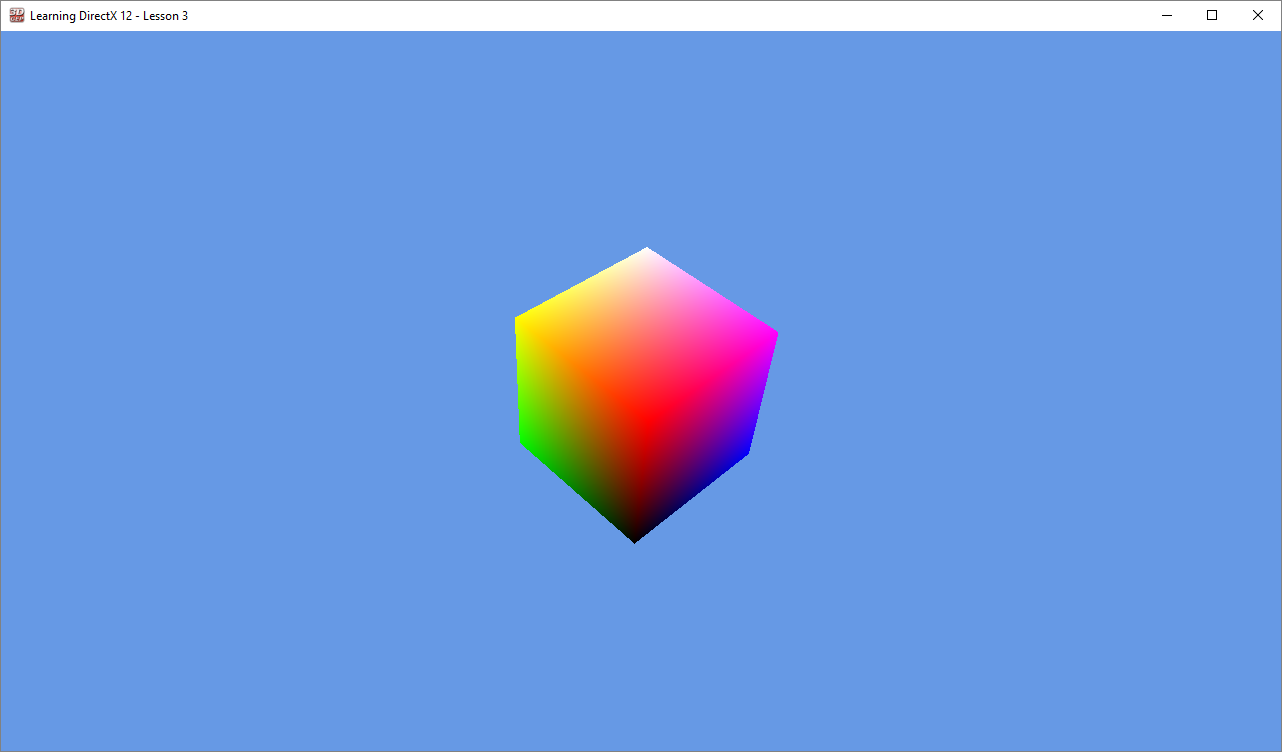
Screenshot of Tutorial 2
Tutorial2::OnKeyPressed
The OnKeyPressed method is called on the Game class whenever the user presses a key on the keyboard while the render window has focus. The method provides a KeyEventArgs structure which contains the key code that was pressed.
|
1 2 3 4 5 6 7 8 9 10 11 12 13 14 15 16 17 18 19 20 21 |
void Tutorial2::OnKeyPressed(KeyEventArgs& e) { super::OnKeyPressed(e); switch (e.Key) { case KeyCode::Escape: Application::Get().Quit(0); break; case KeyCode::Enter: if (e.Alt) { case KeyCode::F11: m_pWindow->ToggleFullscreen(); break; } case KeyCode::V: m_pWindow->ToggleVSync(); break; } } |
Admittedly this not a very interesting function but keyboard events need to be handled somewhere. The following keyboard keys are handled:
- Esc: Pressing Escape causes the application to quit.
- Alt+Enter, F11: Pressing either Alt+Enter or F11 toggles the fullscreen state of the window.
- V: Pressing the V key toggles V-sync mode.
In addition to handling keyboard events, the mouse scroll wheel events are also handled.
|
1 2 3 4 5 6 7 8 9 |
void Tutorial2::OnMouseWheel(MouseWheelEventArgs& e) { m_FoV -= e.WheelDelta; m_FoV = clamp(m_FoV, 12.0f, 90.0f); char buffer[256]; sprintf_s(buffer, "FoV: %f\n", m_FoV); OutputDebugStringA(buffer); } |
The WheelDelta contains the normalized rotation of the mouse wheel. This value is used to increase or decrease the field of view of the camera. To prevent weird distortion of the camera, the field of view should not be allowed to become too small or too large. The field of view is clamped to the range \(\{12^{\circ} \cdots 90^{\circ}\}\)
The new field of view is printed to the debug output in Visual Studio so that it is easy to see what the effect is for the current field of view.
Run the Demo
If you run the demo application, you should see something similar to what is shown below:
Rotating Cube - Click & Drag to rotate cube
Conclusion
Although the result is not that amazing, what you have learned is! Let’s recap what you have learned in this lesson. You learned about resource heaps. You learned the difference between committed, placed, and reserved resources. You learned (more) about the various stages of the rendering pipeline and you’ve learned how to create a Pipeline State Object (PSO) for a graphics pipeline. You’ve also learned about root signatures. You’ve learned about the various types of root parameters (constants, inline descriptors, and descriptor tables). You’ve also been introduced to static samplers that can be written directly into the root signature. To facilitate the DirectX 12 demo application, I’ve also suggested a command queue class that encapsulates all of the synchronization primitives and helper functionality to make working with DirectX 12 command queues easier. You’ve also seen how to create simple vertex and pixel shaders for rendering a cube. Uploading vertex buffer and index buffer data to the GPU has also been described. You were also exposed to the depth buffer and how to bind it to the graphics pipeline as a render target. You’ve also seen how to bind 32-bit constants as a root parameter argument. And finally, you’ve seen how to render geometry using a draw command.
In the next lesson, I will introduce you to textures and I will show you how to implement the basic lighting equation with diffuse and specular components. You will also see more advanced applications of binding resources using descriptors and sending dynamic constant buffer data to the GPU.
Download the Source
The source code for this lesson is available on GitHub:
 https://github.com/jpvanoosten/LearningDirectX12
 Source Code.zip
References
[1] J. van Oosten, “A Journey Through DirectX 12 Dynamic Memory Allocations”, 3dgep.blogspot.nl, 2016. [Online]. Available: https://3dgep.blogspot.nl/2016/02/a-journey-through-directx-12-dynamic.html. [Accessed: 10- Jan- 2018].
[2] C. Crassin, “Dynamic Sparse Voxel Octrees for Next-Gen Real-Time Rendering”, Icare3d.org, 2012. [Online]. Available: http://www.icare3d.org/research-cat/publications/dynamic-sparse-voxel-octrees-for-next-gen-real-time-rendering.html. [Accessed: 10- Jan- 2018].
[3] Microsoft, “Managing Graphics Pipeline State in Direct3D 12 (Windows)”, Msdn.microsoft.com, 2018. [Online]. Available: https://msdn.microsoft.com/en-us/library/dn899196(v=vs.85).aspx. [Accessed: 10- Jan- 2018].
[4] Microsoft, “Using Constants Directly in the Root Signature (Windows)”, Msdn.microsoft.com, 2018. [Online]. Available: https://msdn.microsoft.com/en-us/library/dn899219(v=vs.85).aspx. [Accessed: 23- Jan- 2018].
[5] Microsoft, “Root Signature Limits (Windows)”, Msdn.microsoft.com, 2018. [Online]. Available: https://msdn.microsoft.com/en-us/library/dn899209(v=vs.85).aspx. [Accessed: 23- Jan- 2018].
[6] Microsoft, “Using Descriptors Directly in the Root Signature (Windows)”, Msdn.microsoft.com, 2018. [Online]. Available: https://msdn.microsoft.com/en-us/library/dn899223(v=vs.85).aspx. [Accessed: 23- Jan- 2018].
[7] Microsoft, “DirectXMath (Windows)”, Msdn.microsoft.com, 2018. [Online]. Available: https://msdn.microsoft.com/en-us/library/hh437833(v=vs.85).aspx. [Accessed: 21- Feb- 2018].
[8]Microsoft, “Primitive Topologies (Windows)”, Msdn.microsoft.com, 2018. [Online]. Available: https://msdn.microsoft.com/en-us/library/bb205124(v=vs.85).aspx. [Accessed: 01- Mar- 2018].
[9] Microsoft, “ID3D12Device::CreateCommittedResource method (Windows)”, Msdn.microsoft.com, 2018. [Online]. Available: https://msdn.microsoft.com/en-us/library/dn899178(v=vs.85).aspx. [Accessed: 13- Mar- 2018].
[10] Microsoft, “D3D12_SUBRESOURCE_DATA structure (Windows)”, Msdn.microsoft.com, 2018. [Online]. Available: https://msdn.microsoft.com/en-us/library/dn879485(v=vs.85).aspx. [Accessed: 13- Mar- 2018].
[11] Microsoft, “UpdateSubresources (heap-allocating) function (Windows)”, Msdn.microsoft.com, 2018. [Online]. Available: https://msdn.microsoft.com/en-us/library/dn899213(v=vs.85).aspx. [Accessed: 13- Mar- 2018].
[12] Microsoft, “D3D12_VERTEX_BUFFER_VIEW structure (Windows)”, Msdn.microsoft.com, 2018. [Online]. Available: https://msdn.microsoft.com/en-us/library/dn903819(v=vs.85).aspx. [Accessed: 13- Mar- 2018].
[13]Microsoft, “D3D12_INDEX_BUFFER_VIEW structure (Windows)”, Msdn.microsoft.com, 2018. [Online]. Available: https://msdn.microsoft.com/en-us/library/dn891445(v=vs.85).aspx. [Accessed: 13- Mar- 2018].
[14] Microsoft, “D3D12_INPUT_ELEMENT_DESC structure (Windows)”, Msdn.microsoft.com, 2018. [Online]. Available: https://msdn.microsoft.com/en-us/library/dn770377(v=vs.85).aspx. [Accessed: 13- Mar- 2018].
[15] Microsoft, “Root Signature Version 1.1 (Windows)”, Msdn.microsoft.com, 2018. [Online]. Available: https://msdn.microsoft.com/en-us/library/mt709473(v=vs.85).aspx. [Accessed: 15- Mar- 2018].
[16] Microsoft, “D3D12_ROOT_SIGNATURE_FLAGS enumeration (Windows)”, Msdn.microsoft.com, 2018. [Online]. Available: https://msdn.microsoft.com/en-us/library/dn879480(v=vs.85).aspx. [Accessed: 19- Mar- 2018].
[17] Microsoft, “D3D12_RESOURCE_DESC structure (Windows)”, Msdn.microsoft.com, 2018. [Online]. Available: https://msdn.microsoft.com/en-us/library/dn903813(v=vs.85).aspx. [Accessed: 24- Mar- 2018].
[18] Microsoft, “D3D12_DEPTH_STENCIL_VIEW_DESC structure (Windows)”, Msdn.microsoft.com, 2018. [Online]. Available: https://msdn.microsoft.com/en-us/library/dn770357(v=vs.85).aspx. [Accessed: 24- Mar- 2018].
[19] Microsoft, “ID3D12Device::CreateDepthStencilView method (Windows)”, Msdn.microsoft.com, 2018. [Online]. Available: https://msdn.microsoft.com/en-us/library/dn788661(v=vs.85).aspx. [Accessed: 24- Mar- 2018].
[20] Microsoft, “ID3D12GraphicsCommandList::IASetVertexBuffers method (Windows)”, Msdn.microsoft.com, 2018. [Online]. Available: https://msdn.microsoft.com/en-us/library/dn986883(v=vs.85).aspx. [Accessed: 28- Mar- 2018].
[21] Microsoft, “ID3D12GraphicsCommandList::RSSetViewports method (Windows)”, Msdn.microsoft.com, 2018. [Online]. Available: https://msdn.microsoft.com/en-us/library/dn903900(v=vs.85).aspx. [Accessed: 28- Mar- 2018].
[22] Microsoft, “ID3D12GraphicsCommandList::OMSetRenderTargets method (Windows)”, Msdn.microsoft.com, 2018. [Online]. Available: https://msdn.microsoft.com/en-us/library/dn986884(v=vs.85).aspx. [Accessed: 29- Mar- 2018].
[23] Microsoft, “ID3D12GraphicsCommandList::SetGraphicsRoot32BitConstants method (Windows)”, Msdn.microsoft.com, 2018. [Online]. Available: https://msdn.microsoft.com/en-us/library/dn903910(v=vs.85).aspx. [Accessed: 29- Mar- 2018].
[24] Microsoft, “ID3D12GraphicsCommandList::DrawIndexedInstanced method (Windows)”, Msdn.microsoft.com, 2018. [Online]. Available: https://msdn.microsoft.com/en-us/library/dn903874(v=vs.85).aspx. [Accessed: 04- Apr- 2018].
Thank you very much for taking the time to present such a well laid out and structured tutorial. So much depth is often squeezed into overwhelming walls of text rather than spread out so methodically. I’m just beginning my journey from DirectX11 to 12 and am extremely grateful for your writings, teasing apart the detail which is skipped or merely eluded to elsewhere.
I’m a professional programmer who has been tasked with a large upgrade task, and having found DirectX11 lacking in synchronisation I was almost forced upon DirectX12. At least with your writings I now have a decent understanding of the fundamentals, leading to a greater confidence on my own journey.
Best wishes for whatever journeys you find yourself on.
This is very well explained, and can be understand waiting for more and hungry for knowledge 🙂
I have only one question at this point. For example when I have loaded few 3D models which some have textures and some not, i have to create separate function for texture and color in shader and set different PSO for each or handle it by a bool/int parameter sent to shader function?
I read on a NVIDIA doc that there shouldn’t be too much changes of PSO on runtime so if it is handled be different PSO’s should I sort obkjects loaded with either it has a texure or not?
Maxim,
Minimizing PSO changes is definitely a good idea. Depending on the hardware, conditionals in shaders could be expensive. You will need to check the performance characteristics of your shaders using profiling tools to determine if using conditionals in the shader leads to poor performance. Newer GPUs tend to be better at it.
A rule of thumb: If all shader invocations follow the same code path, the cost of the conditional is (probably) negligible. If some invocations follow different branches, then the shader has the cost of following all branches. If your conditionals are based on constant data in the material, it is probably okay.
See Texturing and Lighting in DX11 for examples of an “uber shader” that can be used for both textured, and non-textured materials.
Thank you! The amount of new things to learn in DX12 is insane. It’s hard for me to find good resources for this API.
I am definitely waiting for more DX12 lessons 🙂
Any plans on making a part 3 to your serie ?
These articles are by far the greatest DX12 resources available.
Keep up the good work !
Part 3 is in progress. My summer vacation has delayed the progress of writing part 3!
Hi,
Is there any info about upcoming parts of this tutorial?
Mateusz,
Part 3 is still in progress. I’ve decided to focus on creating a DX12 framework that simplifies working with dynamic geometry (vertex / index / constant buffers), CPU and GPU descriptor management, and resource state tracking. I’m currently in the process of writing this post.
I’ve decided to do this to simplify later posts which can focus more on various rendering techniques without getting bogged down with descriptor and resource state management. However, this post is taking a lot longer than normal (probably because the content is complex and I’m trying to find a way to make it as simple and understandable as possible for beginning graphics programmers).
The complexity of the topic, my full-time teaching job, and family life have all contributed to the delay of this post, but I hope to publish it soon!
The article is great , from which I benefit. I hope you can post the part 3 earily.
Many thanks for the tutorial!
I am not clear on why we don’t need a resource barrier somewhere for the vertex and index buffer resources – will they not still be in the D3D12_RESOURCE_STATE_COPY_DEST state when rendering?
James,
See the reply below in this comment comment.
Many thanks for the tutorial – look forward to the next part!
I am not clear on why the index/vertex buffer resources did not need a resource barrier to transition them from
D3D12_RESOURCE_STATE_COPY_DESTtoD3D12_RESOURCE_STATE_INDEX_BUFFER/D3D12_RESOURCE_STATE_VERTEX_AND_CONSTANT_BUFFER. Are we just getting away with it because the requirement to set the correct states isn’t strict? Or have I misunderstood something?James,
Good catch! The vertex and index buffers do not need an explicit resource barrier because resources used on a copy queue (or buffer resources used on any queue type) will automatically decay to the
D3D12_RESOURCE_STATE_COMMONresource state when the GPU finishes execution ofID3D12CommandQueue::ExecuteCommandLists. Resource state decay to theCOMMONstate is free and no additional resource barrier is required.Index and vertex buffers will be automatically promoted from the
D3D12_RESOURCE_STATE_COMMONto theD3D12_RESOURCE_STATE_INDEX_BUFFERandD3D12_RESOURCE_STATE_VERTEX_AND_CONSTANT_BUFFERstates (respectively) when first used on a GPU queue.This is called implicit state transitions and is further explained here: Implicit State Transitions.
This is not right. If you enable GPU Based Validation, you will get a warning, telling you that Resources used in COPY command lists must start out in the D3D12_RESOURCE_STATE_COMMON state.
So either, we should use a DIRECT command list to create resources or set the resource state to COMMON if you are going to use a COPY command list
Gaktan,
Thanks for pointing this out. I only realized that this issue when I enabled GPU validation in the debug settings. It is not detected when you simply enable debug settings (without validation) so I didn’t even realize it was an issue.
I have since fixed this issue and you can see this in the DX12Lib project but I did not go back and update this tutorial (yet). To fix it, I always create the resource in the COMMON state (regardless of command list type) and always transition to the correct state depending on how the resource is being used (see the 3rd tutorial for the class that I use to manage resource states across multiple command lists: Learning DirectX 12 – Lesson 3 – Framework)
Hi Jeremiah! Thanks a lot for you articles, you explaining more detailed than some DirectX big books, where I can’t find answers for a lot of questions – ‘why’. So, I’ve got answers from your articles to understand how DirectX 12 works under hood. I try to improve my CG programming skills and transferring from OpenGL to DirectX 12 now. And I have a question about: “Try to reason about why the swap chain requires multiple back buffers (at least 2) but only a single depth-stencil buffer is needed for correct rendering. Does the depth-stencil buffer ever need to be in both a read and write state at the same time?”. So, how I understand, when we call ExecuteCommandList, commands from second frame won’t be processed on GPU until first frame commands will be executed (if we not using multi GPU feature). So depth buffer will be available on GPU for read/write on second frame because of this reason. And we needs in 2 or more color buffers for swap chain because when we start executing commands on second frame, first frame will be presenting at this time. Please correct me if I wrong, because I want to understand it finally and set all points on i. Shame on me, but I never thought why we using single depth buffer only, while working with OpenGL, but this process is similar I think. Thank you for your work, it’s really helpful!
Artem,
Yes, your reasoning is correct. Since we are only using a single command queue for rendering, then all of the rendering commands are executed serially in the queue so the depth buffer will not be accessed by multiple queues at the same time. The reason why we need multiple color buffers is because we can’t write the next frame until the Windows Driver Display Model (WDDM) is finished presenting the frame on the screen. Stalling the CPU thread until the frame is finished being presented is not efficient so to avoid the stall, we simply render to a different (front) buffer. Since the depth buffer is not used by WDDM, we don’t need to create multiple depth buffers!
Many thanks, this is a great series.
very minor:
in the pixel shader section: “VertexShader.hlsl” should be “PixelShader.hlsl”
Martin,
Great catch. This has been fixed!
Great article,
I tried to get the code working adding all like described in the article. I used the right Win10 SDK version. It didn’t work for me – at some point I downloaded the same and I didn’t compile with compile errors. I had VS2017 and VS2019 install and was using 2019. I managed to get rid of most errors (I assume VS2019 differences) but some remained. Finally I uninstalled VS2017 and it compiled. I did get an error with alignment and I had to define (VS behavior changed and the define allows to use new or old behavior):
#define _ENABLE_EXTENDED_ALIGNED_STORAGE
It compiled but crashed in
XMMATRIX mvpMatrix = XMMatrixMultiply(m_ModelMatrix, m_ViewMatrix);
because local/stack variable cannot be forced to be aligned. Adding some code before to debug it made it work sometimes. adding the define in the project defined works in release but not in debug (likely it’s random and release was working)
I found a similar post to my problem and posted the issue there: https://developercommunity.visualstudio.com/content/problem/425273/enabling-enable-extended-aligned-storage-in-a-mixe.html?inRegister=true
It sounds like you are trying to build using 32-bits. Make sure you are using the x64 architecture when building the libs and application. If you use the
GenerateProjectFiles.batscript, then it should a (using the included CMake utility) configure the project to build as a 64-bit library and executable.I advise you not to try to use 32-bit builds for DirectX 12 but only use 64-bits.
The crash occurs because the
m_ModelViewandm_ViewMatrixare not aligned correctly to 16 byte addresses. Variables defined on the stack (mvpMatrixin this case) should respect the 64-byte alignment requirements specified on the structure (the XMMATRIX type specifies a 16 byte alignment) but the alignment of class member variables is not guaranteed to be aligned correctly since the memory allocator only looks at the size of the type when allocating (which doesn’t guarantee the alignment of the members of the class!)To solve this issue, I usually use aligned_alloc to allocate a structure that contains the DirectX Matrices but I guess I overlooked it in this case.
Compiling for 64-bits will solve this problem anyways.
Hi Jeremiah! Thanks a lot for you articles! From your sample and I know how to bind one no-msaa texture to RT, but what can I do if I want to bind msaa4x texture to RT?
Before you can use 4xMSAA, you need to make sure your GPU supports it. See
Application::GetMultisampleQualityLevelsfor an example of how to get the best quality level supported by your GPU.Then you need to create a texture with the sample count and quality supported by your GPU.
See Learning DirectX 12 – Lesson 3 – Framework for an example for rendering with MSAA.
The source code for creating a MSAA render target can be found here: https://github.com/jpvanoosten/LearningDirectX12/blob/master/Tutorial3/src/Tutorial3.cpp#L197.
I hope this helps.
Where to look for MSAA in Lesson 3?
Regards
Brento,
MSAA is not really discussed in the articles but if you take a look at the sample code for Tutorial 3 (https://github.com/jpvanoosten/LearningDirectX12/blob/v0.0.3/Tutorial3/src/Tutorial3.cpp), You’ll see how I handle MSAA for the demo.
Thank you for sharing this.
As others have said, your tutorials have been outstanding. But I have trouble getting the source. Since the Application module was to large to include directly in your posting, I’ve tried getting the zipped source from GIT. Problem is none of the four code/header modules are included in the zip file, only main and tutorial2. Could you explain how to retrieve all the modules to compile this project?
Thank you
Terry,
The project uses CMake to generate the project and solution files for the project. There should be a “GenerateProjectFiles.bat” batch file that can be used to generate the project files for Visual Studio (just double-click the batch file). You must have Visual Studio already installed for the script to work. The CMake executable is included in the project files (in case you don’t already have CMake installed locally).
I hope this helps.
My apologies, posted a comment yesterday about missing source files in the zip for this tutorial that was in error. Started reading the third tutorial and realized that I should look at the DX12Lib directory for what I thought was missing. Consider it an old programmers wanderings. Have a Happy Holiday and continue the great work!
No problem, I answered your question anyways. I hope it helps others.
it looks like m_DepthBuffer need to call ReleaseAndGetAddressOf in ResizeDepthBuffer when CreateCommittedResource because ReportLiveObjects throws exception if depth buffer not relesed before recreate.
m_DepthBufferis aComPtr. Using the “address of” operator&m_DepthBufferwill release the original object and get the address of the pointed to object.I just ran the demo again, and I did not get any reported unreleased objects with
ReportLiveObjects.Did you make any changes to the code?
Hi , I really wonder why we should signal Gpu again and increase m_FenceValue when we flush gpu instead of waiting for m_FenceValue that should be the latest fence value associated with current command allocators, to my opinion, waiting for m_FenceValue to the end indicates that the gpu has done all of its pending job, am I wrong ?
void CommandQueue::Flush()
{
WaitForFenceValue(Signal());
}
If the end user never used Signal before, then there won’t be a signal on the command queue to wait for.
When we flush the command queue, we want to make sure all operations are complete before continuing (for example, when resizing the swap chain or exiting the application) regardless if the user signaled after executing the last command list or not (as signaling the command queue is not required!)
Is the application class available anywhere? It’s not included here and the link provided doesn’t work.
You can download the source. All the links are here: https://www.3dgep.com/learning-directx-12-2/#Download_the_Source
I get an unhandled exception when in the CreateCommittedResource call in the UpdateBufferResource
Unhandled exception at 0x00007FFF69654FFC (KernelBase.dll) in Tutorial2.exe: 0x0000087A (parameters: 0x0000000000000002, 0x0000001291FDBED0, 0x0000001291FDDCA0).
I tried to download and run the project from Github and I get the same error. I have built with CMake 3.24 and VS 2022
I can continue through the exception and the HRESULT value is S_OK as well
Update the
DenyIdslist inApplication.cppto includeD3D12_MESSAGE_ID_CREATERESOURCE_STATE_IGNORED:D3D12_MESSAGE_ID DenyIds[] = {
D3D12_MESSAGE_ID_CLEARRENDERTARGETVIEW_MISMATCHINGCLEARVALUE, // I’m really not sure how to avoid this message.
D3D12_MESSAGE_ID_MAP_INVALID_NULLRANGE, // This warning occurs when using capture frame while graphics debugging.
D3D12_MESSAGE_ID_UNMAP_INVALID_NULLRANGE, // This warning occurs when using capture frame while graphics debugging.
D3D12_MESSAGE_ID_CREATERESOURCE_STATE_IGNORED, // This triggers a break exception during the first call to CreateCommittedResource.
};
I believe you are getting this warning when a resource is created in a default heap and the initial state is not
D3D12_RESOURCE_STATE_COMMON. This is fixed in later versions of the repo, but for v0.0.2 tag, you will need to change theTutorial2.cppfile:Small optimisation suggestion. The view matrix does not need to be updated every frame in
OnUpdate(), as we never change it in this tutorial. It should be only calculated once, in someinit()function for the tutorial. Also, the perspective matrix calculation should be moved to the mouse scroll wheel handler, as it can only be changed when scrolling the well, there is no point to recalculate it every frame.Thanks for this tutorial!
How do we incorporate the idea of frames in flight in this app?
Frame synchronization was covered in the first lesson (Learning DirectX 12 – Lesson 1 – Initialize DirectX 12. Check out the section on GPU Synchronization.
There may be a typo in section 9.5.6:
“””
… Before the pipeline shader object (PSO) can be created, the root signature needs to be defined…
“””
Maybe the term
pipeline shader object (PSO)should bepipeline state object (PSO)?Thanks for this excellent tutorial and all other brilliant articles!
Good catch! Fixed!