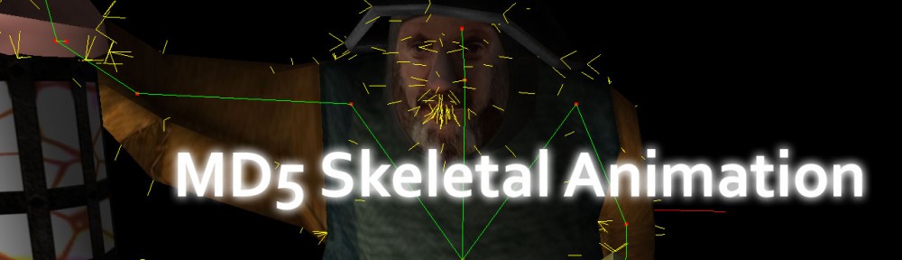

Bob with Lamp
In this article, I will show how you can load and animate models loaded from the MD5 model file format. In this article I will use OpenGL to render the models. I will not show how to setup an OpenGL application in this article. If you need to get a quick introduction on setting up an OpenGVL application, you can follow the “Beginning OpenGL for Game Programmers” article [here].
Introduction
The MD5 Model format has been used by several commercial game projects including ID software’s Doom 3
Dependencies
A few dependencies are used by this project to ease the coding process and to make the material more readable.
- OpenGL Utility Toolkit (GLUT): Is used for platform-independent window management and window event handling that simplifies the implementation of an OpenGL windowed application.
- OpenGL Mathmatics Library (GLM): Used for vector classes, quaternion classes, matrix classes and math operations that are suited for OpenGL applications.
- Simple OpenGL Image Library (SOIL): A library that provides functions to load textures from disc as easy as possible. This library is ideal for loading images to be used by OpenGL.
- boost (1.46.0): The boost::filesystem library is used to resolve paths, decompose paths, and open files in a platform independent way.
All of the dependencies are provided together with the source files and project files that are needed to build the demo in Visual Studio 2008 and Visual Studio 2010.
MD5 Model Format
A fully animated MD5 model asset consists of two different files.
- The .md5mesh file: describes the geometry and materials that are used to display the model.
- The .md5anim file: describes a single animation that can be applied to the model described in the .md5mesh file.
The two files must match the number and name of joints to be valid.
The .md5mesh File
The .md5mesh file is used to describe the geometry and materials that are used to display the model. This file consists of a header, a single “joints” section and any number of “mesh” sections.
The format of the .md5mesh file is:
|
1 2 3 4 5 6 7 8 9 10 11 12 13 14 15 16 17 18 19 20 21 22 23 24 25 26 27 28 |
MD5Version <int:version> commandline <string:commandline> numJoints <int:numJoints> numMeshes <int:numMeshes> joints { <string:name> <int:parentIndex> ( <vec3:position> ) ( <vec3:orientation> ) ... } mesh { shader <string:texture> numverts <int:numVerts> vert <int:vertexIndex> ( <vec2:texCoords> ) <int:startWeight> <int:weightCount> ... numtris <int:numTriangles> tri <int:triangleIndex> <int:vertIndex0> <int:vertIndex1> <int:vertIndex2> ... numweights <int:numWeights> weight <int:weightIndex> <int:jointIndex> <float:weightBias> ( <vec3:weightPosition> ) ... } ... |
The .md5mesh Header
An example of the header is shown below:
|
1 2 3 4 5 |
MD5Version <int:version> commandline <string:commandline> numJoints <int:numJoints> numMeshes <int:numMeshes> |
The header consists of the MD5 version this file describes, a command-line argument that was used to generate the mesh file, the number of joints described in this file, and the number of meshes that this file defines.
For the model loader described in this article, the “MD5Version” tag must always be “10”. I will not cover different versions of the MD5 file format in this article and will assume this value is always “10”.
The next line describes the command-line arguments that were used to export the mesh file from the Digital Content Creation (DCC) tool such as Maya, 3D Studio Max, or Blender.
The next two lines “numJoints“, and “numMeshes” describe how many joints and meshes that are defined in this file.
The “joints” section
An example of the “joints” section is shown below:
|
1 2 3 4 |
joints { <string:name> <int:parentIndex> ( <vec3:position> ) ( <vec3:orientation> ) ... } |
Immediately following the “numJoints” and “numMeshes” parameters is the “joints” section. The “joints” section starts with the word “joints” and an open-brace ‘{‘ character followed by “numJoints” joint definitions. These joints define the skeleton of the model in the bind pose.
Each joint is defined on a single line and begins with the name of the joint enclosed in double-quotes. The next parameter following the name of the joint is the index of the joint’s parent in the skeletal hierarchy. The only joint that does not have a parent is the root joint, in which case the joint’s parent index will be “-1”.
After the parent’s index, the joint’s position and orientation are described as 3-component vectors enclosed in parenthesis “( x y z )”. Each component of the vector is separated by a space. The first vector is the position of the joint in object local space, and the second vector is the orientation of the joint in object local space. The orientation is a quaternion which actually requires 4-components to be fully defined. The w-component of the orientation quaternion will be computed manually which will be shown later.
The “mesh” section
An example of the “mesh” section is shown below:
|
1 2 3 4 |
mesh { shader <string:texture> ... } |
Following the “joints” section, there is a “mesh” section for each of the meshes described in the model file. The “mesh” section begins with the word “mesh” and an open-brace ‘{‘ character.
The first parameter in the “mesh” section is the “shader” parameter. It’s value is the relative path to a texture which can be applied to the mesh. Depending on the exporter, this path could be relative to the root folder of the archive where the mesh was loaded from, or it could be relative to the .md5mesh file, or it could also be an absolute path on the computer where the mesh was originally exported (in this case, you will need to edit the texture path manually before importing the mesh if the file path doesn’t exist in your environment). The texture path may or may not have an extension. Your model loader should account for this by adding the default texture extension to the file path before requesting the texture from the the texture manager. More on this will be handled later when I describe the source code for the loader.
Following the “shader” parameter is the vertex definitions. The first parameter before the vertex array is the “numverts” parameter which defines how many vertices this mesh contains.
|
1 2 3 |
numverts <int:numVerts> vert <int:vertexIndex> ( <vec2:texCoords> ) <int:startWeight> <int:weightCount> ... |
A single vertex definition consists of the word “vert” followed by the index of the vertex in the vertex array. Immediately following the vertex index is a 2-component vector enclosed in parenthesis “( s t )” that defines the texture coordinates of the vertex. Following the texture coordinate are two integer values that describe the start index of the weight, and the number of weights that are associated with this vertex. Each vertex can be weighted to one or more joints in the skeletal hierarchy of the model. The final position of the vertex is determined by summing the positions of the joints and the positions of the weights multiplied by the bias of the weight. Weight definitions will be described later.
Following the vertex array is the triangle array. A triangle is defined by a 3-tuple set of vertex indexes in the vertex array. The triangle array starts with the “numtris” parameter which describes how many triangles this mesh defines.
|
1 2 3 |
numtris <int:numTriangles> tri <int:triangleIndex> <int:vertIndex0> <int:vertIndex1> <int:vertIndex2> ... |
Each triangle definition appears on a single line of the file. The triangle definition starts with the word “tri” immediately followed by the index of the triangle in the triangle array. The next three integers in the triangle definition describe the index of the vertices in the vertex array that make up this triangle.
Following the triangle definitions is the weights array. Each weight describes how much of a single vertex is associated with each joint in the model’s skeleton. The weights array starts with the “numweights” parameter which describes the number of weights that are to be read.
|
1 2 3 |
numweights <int:numWeights> weight <int:weightIndex> <int:jointIndex> <float:weightBias> ( <vec3:weightPosition> ) ... |
Each weight definition appears on a single line. The weight definition starts with the word “weight” and is immediately followed by the index of the weight in the weight array. Following the weight index is the joint index in the joints array that this weight is associated with. The “weightBias” parameter is a ratio that determines how much of the joint’s orientation and position is applied to the vertex’s final position. The “weightPosition” parameter is a 3-component vector which describes the position of the weight in joint-local space and must be rotated by the joint’s orientation and added to the joint’s position before being applied to the final vertex position. This algorithm will be described in more detail when I show the code that builds the mesh’s vertex array.
The .md5anim File
The .md5anim file describes a single animation cycle that can be associated with a model. The .md5anim file consists of several sections that are used to describe the animation. The first section is the header which describes the content of the rest of the file. following the header is the “hierarchy” section which describes the joints defined in this animation and must be consistent with the joints that are described in the .md5mesh file that this animation is associated with. The next section is the “bounds” section which defines an axis-aligned bounding box of the mesh for each frame of the animation. The “baseframe” section defines the default position and orientation of each joint in the skeleton. And finally there is a “frame” section for each frame that makes up the animation.
The model’s bindpose skeleton is defined in the model’s “joints” section.
The format of the .md5anim file is as follows:
|
1 2 3 4 5 6 7 8 9 10 11 12 13 14 15 16 17 18 19 20 21 22 23 24 25 26 27 |
MD5Version <int:version> commandline <string:commandline> numFrames <int:numFrames> numJoints <int:numJoints> frameRate <int:frameRate> numAnimatedComponents <int:numAnimatedComponents> hierarchy { <string:jointName> <int:parentIndex> <int:flags> <int:startIndex> ... } bounds { ( vec3:boundMin ) ( vec3:boundMax ) ... } baseframe { ( vec3:position ) ( vec3:orientation ) ... } frame <int:frameNum> { <float:frameData> ... } ... |
The .md5anim Header
The first section of the .md5anim file is the file header. The header describes the rest of the content that is contained in the animation file. The header consists of the version of this file, the command line that was used to export this file from the DCC software, the number of frames that defines the animation, the number of joints in the skeletal hierarchy, the frame-rate of the animation, and the number of animated components that defines each frame section.
|
1 2 3 4 5 6 7 |
MD5Version <int:version> commandline <string:commandline> numFrames <int:numFrames> numJoints <int:numJoints> frameRate <int:frameRate> numAnimatedComponents <int:numAnimatedComponents> |
The “MD5Version” parameter defines the version of the file. In this demo, I will assume this version number is always “10”.
The “commandline” parameter describes the command-line arguments that were used to export this animation from the DCC software. This value will be ignored in the demo application.
The “numFrames” parameter described the number of “frame” sections that this animation will define.
The “numJoints” parameter describes the number of joints that are described in the “hierarchy” section.
The “frameRate” parameter defines the number of frames per second that this animation was created with. The actual amount of time between each frame can be calculated by taking the reciprocal of the frame-rate.
The “numAnimatedComponents” parameter defines the number of components that each “frame” section defines. The frame components will be used later to describe the final position and orientation of the skeleton for each frame of the animation.
The “hierarchy” Section
The “hierarchy” section defines the joints of the skeleton in this animation. The number of the joints and the name of the joints in the “hierarchy” section must match the number and names of the joints described in the model files’s “joints” section.
An example of the “hierarchy” section is shown below:
|
1 2 3 4 |
hierarchy { <string:jointName> <int:parentIndex> <int:flags> <int:startIndex> ... } |
Each joint in the hierarchy appears on one line of the file. The joint definition starts with the name of the joint as a string enclosed in quotes. Following the string name is an index of the the joint’s parent in the joints array. The root joint will be the only joint without a valid parent so it’s parent’s index will be “-1”. Following the parent index is the “flags” value which describes how this joint’s position and orientation will be built-up based on the frame data described later. The last parameter in the joint definition is the first index of the data array defined in the frame data.
Following the “hierarchy” section is the “bounds” section. The “bounds” section describes an axis-aligned bounding box that defines the dimensions of the model for each frame of the animation. An example of the “bounds” section is shown below.
|
1 2 3 4 |
bounds { ( vec3:boundMin ) ( vec3:boundMax ) ... } |
Each line of the “bounds” section describes the bounding box’s minimum and maximum points that describe the bounding box of the model for a single frame. Each of the min, and max points for the bounding box is 3-component vector described in object local space.
The “baseframe” section describes the default position and orientation of each joint before the frame data is applied. Each position and orientation is described relative to the joint’s parent. To build the final skeleton joint in object-local space, you have to add the position and orientation of the joint’s parent. An example of the “baseframe” section is:
|
1 2 3 4 |
baseframe { ( vec3:position ) ( vec3:orientation ) ... } |
Each line of the “baseframe” section describes a joint’s default position and orientation. Since the orientation is defined as a quaternion, 4-components are required to describe the orientation. The w-component of the quaternion will be calculated manually when the joint for the skeleton frame is built. This algorithm will be shown later in the article.
Following the “baseframe” section is the “frame” sections. There is one “frame” section for each frame of the animation defined by the “numFrames” parameter. An example of the “frame” section is shown below:
|
1 2 3 4 |
frame <int:frameNum> { <float:frameData> ... } ... |
Each “frame” section starts with the word “frame” followed by the frame number that this frame describes. The frame numbers increase sequentially from 0 to (numFrames – 1). The “frame” section consists of a series of floating-point values that describe the frame data. The number of floating point values in each frame is determined by the “numAnimatedComponents” parameter read in the header.
Now that we’ve seen the format of the MD5 model and animation files, let’s see how we can create CPP class files to read-in and render the MD5 model at runtime.
The MD5Model Class
The MD5Model class is used to parse the .md5mesh files and to store the data at runtime. It is also going to be responsible for holding the list of animations that are applied to the model. In a production environment, it may be appropriate to have a global animation manager class that will store all the animations that can be applied to different MD5Model classes with the same skeleton. For this demo, I am going to neglect these optimizations for the sake of clarity and ease of implementation. The MD5Model class will also provide functionality to render the model in OpenGL.
The contents of the header file for the MD5Model class are shown below.
|
1 2 3 4 5 6 7 8 9 10 11 12 13 14 15 16 17 18 19 20 21 22 23 24 25 26 27 28 29 30 31 32 33 34 35 36 37 38 39 40 41 42 43 44 45 46 47 48 49 50 51 52 53 54 55 56 57 58 59 60 61 62 63 64 65 66 67 68 69 70 71 72 73 74 75 76 77 78 79 80 81 82 83 84 85 86 87 88 89 90 91 92 93 94 95 96 97 98 99 100 101 102 103 |
#pragma once; #include "MD5Animation.h" class MD5Model { public: MD5Model(); virtual ~MD5Model(); bool LoadModel( const std::string& filename ); bool LoadAnim( const std::string& filename ); void Update( float fDeltaTime ); void Render(); protected: typedef std::vector<glm::vec3> PositionBuffer; typedef std::vector<glm::vec3> NormalBuffer; typedef std::vector<glm::vec2> Tex2DBuffer; typedef std::vector<GLuint> IndexBuffer; struct Vertex { glm::vec3 m_Pos; glm::vec3 m_Normal; glm::vec2 m_Tex0; int m_StartWeight; int m_WeightCount; }; typedef std::vector<Vertex> VertexList; struct Triangle { int m_Indices[3]; }; typedef std::vector<Triangle> TriangleList; struct Weight { int m_JointID; float m_Bias; glm::vec3 m_Pos; }; typedef std::vector<Weight> WeightList; struct Joint { std::string m_Name; int m_ParentID; glm::vec3 m_Pos; glm::quat m_Orient; }; typedef std::vector<Joint> JointList; struct Mesh { std::string m_Shader; // This vertex list stores the vertices in the bind pose. VertexList m_Verts; TriangleList m_Tris; WeightList m_Weights; // A texture ID for the material GLuint m_TexID; // These buffers are used for rendering the animated mesh PositionBuffer m_PositionBuffer; // Vertex position stream NormalBuffer m_NormalBuffer; // Vertex normals stream Tex2DBuffer m_Tex2DBuffer; // Texture coordinate set IndexBuffer m_IndexBuffer; // Vertex index buffer }; typedef std::vector<Mesh> MeshList; // Prepare the mesh for rendering // Compute vertex positions and normals bool PrepareMesh( Mesh& mesh ); bool PrepareMesh( Mesh& mesh, const MD5Animation::FrameSkeleton& skel ); bool PrepareNormals( Mesh& mesh ); // Render a single mesh of the model void RenderMesh( const Mesh& mesh ); void RenderNormals( const Mesh& mesh ); // Draw the skeleton of the mesh for debugging purposes. void RenderSkeleton( const JointList& joints ); bool CheckAnimation( const MD5Animation& animation ) const; private: int m_iMD5Version; int m_iNumJoints; int m_iNumMeshes; bool m_bHasAnimation; JointList m_Joints; MeshList m_Meshes; MD5Animation m_Animation; glm::mat4x4 m_LocalToWorldMatrix; }; |
The header starts by including the MD5Animation class definition. This class will be shown later, but at this time you only have to know that this class will hold the information necessary to describe a single animation that is associated with the model.
On line 11, the class’s public functions are defined. The LoadModel function will load the model’s mesh data from a .md5mesh file. The LoadAnim function will load the animation data from a .md5anim file and store the animation data in the MD5Animation instance. The Update and Render methods will update the animation and render the animated model.
On line 17, types are defined for the position, normal, texture, and index buffers that are used to render the model’s meshes in OpenGL. Each mesh will have it’s own buffers that describe the mesh’s geometry.
Starting on line 22 structures are defined to store the information defined in the .md5mesh file that was described earlier. I won’t repeat what was said in the section that described the .md5mesh file format. The only addition to these structures is the Mesh structure that adds the members that are necessary the render the mesh in OpenGL at runtime and the Vertex structure that adds a member variable to store the vertex normal in the vertex’s bind pose in joint-local space. The final vertex normal of the animated mesh will be calculated based on the vertex’s bind pose normal. This is necessary to perform proper lighting calculations on the animated mesh’s vertices.
The PrepareMesh method is used to compute the mesh’s vertex positions based in the joint and weight information and to populate the position, and texture buffers.
The PrepareNormals method is used to pre-compute the mesh’s normals in the bind-pose as well as the normals defined in joint-local space that will be used to quickly calculate the new normals of the animated model.
The RenderMesh method will render a single mesh of the model using OpenGL.
The RenderNormals and RenderSkeleton methods are primarily used to debug the loaded joints and computed normals of the mesh. If the lighting doesn’t look right on the mesh, in most cases it’s because the normals are not computed correctly. The RenderNormals method can be used to determine if the normals are pointing in the right direction and are computed correctly.
The CheckAnimation method will make sure that the loaded animation is appropriate for this particular model file. If the animation skeleton hierarchy doesn’t match with this model’s joints array, the animation will be ignored and the model will simply appear in it’s bind pose.
Starting from line 90 a few private member variables will be defined that will be used to load and display the model.
The MD5Model::LoadModel Method
The MD5Model::LoadModel method is used to load the .md5mesh file and store the data in runtime structures. This method takes as its only parameter a string that describes the location of the .md5mesh file to be loaded. The method will return true if everything went okay, or false if the file could not be loaded.
The first thing this method does is to check the validity of the file name parameter passed to the function. It does this using the boost::filesystem library functions.
|
19 20 21 22 23 24 25 26 27 28 29 30 31 32 33 34 35 36 |
bool MD5Model::LoadModel( const std::string& filename ) { if ( !fs::exists(filename) ) { std::cerr << "MD5Model::LoadModel: Failed to find file: " << filename << std::endl; return false; } fs::path filePath = filename; // store the parent path used for loading images relative to this file. fs::path parent_path = filePath.parent_path(); std::string param; std::string junk; // Read junk from the file fs::ifstream file(filename); int fileLength = GetFileLength( file ); assert( fileLength > 0 ); |
If the file exists and the file size is greater than zero, we will continue to parse the file.
The parent_path variable is used to prefix the texture path in the case the shader parameter points to a texture with a relative path. The param variable is used to store the current parameter in the parsed file and the junk variable is used to read unused data from the file stream.
Before we start loading the data, I want to make sure that the current joints and mesh arrays are empty so we don’t append more joints and meshes of a previously loaded model file.
|
38 39 40 41 42 43 44 |
m_Joints.clear(); m_Meshes.clear(); file >> param; while ( !file.eof() ) { |
On line 41, we’ll read-in the first parameter as a string and while we haven’t reached the end of the file, we’ll continue to parse the file.
The first section of the file we will parse is the header described earlier which includes the MD5Version parameter, the commandline parameter, the numJoints parameter, and the numMeshes parameter.
|
45 46 47 48 49 50 51 52 53 54 55 56 57 58 59 60 61 62 63 |
if ( param == "MD5Version" ) { file >> m_iMD5Version; assert( m_iMD5Version == 10 ); } else if ( param == "commandline" ) { IgnoreLine(file, fileLength ); // Ignore the contents of the line } else if ( param == "numJoints" ) { file >> m_iNumJoints; m_Joints.reserve(m_iNumJoints); } else if ( param == "numMeshes" ) { file >> m_iNumMeshes; m_Meshes.reserve(m_iNumMeshes); } |
Since I will only handle MD5 files of version “10”, in this implementation, I simply assert if the version parameter is anything other than “10”. Ideally, you might want to log an error message and return false if the version is not “10”.
Since the commandline parameter will not be used in this demo, I use the IgnoreLine helper method to ignore the rest of the current line in the file.
In the case of numJoints or numMeshes parameter, I store the value in the appropriate member variable and reserve enough space in the arrays to store the input data.
After the header content has been read-in, the “joints” and “mesh” sections will be parsed. Let’s first look at the “joints” section.
|
64 65 66 67 68 69 70 71 72 73 74 75 76 77 78 79 80 81 82 |
else if ( param == "joints" ) { Joint joint; file >> junk; // Read the '{' character for ( int i = 0; i < m_iNumJoints; ++i ) { file >> joint.m_Name >> joint.m_ParentID >> junk >> joint.m_Pos.x >> joint.m_Pos.y >> joint.m_Pos.z >> junk >> junk >> joint.m_Orient.x >> joint.m_Orient.y >> joint.m_Orient.z >> junk; RemoveQuotes( joint.m_Name ); ComputeQuatW( joint.m_Orient ); m_Joints.push_back(joint); // Ignore everything else on the line up to the end-of-line character. IgnoreLine( file, fileLength ); } file >> junk; // Read the '}' character } |
The “joints” section begins with the open-brace ‘{‘ character followed by the joint definitions, one on each line. For each joint, the name of the joint is read in, followed by the joint’s parent ID, and then followed by the joint’s position and orientation in object local space.
Before we commit the joint to the joints array, the double-quotes around the name string will be removed and the w-component for the orientation quaternion will be computed. The ComputeQuatW helper function will be used to compute the w-component of the quaternion that was just read in. The ComputeQuatW assumes that the resulting quaternion is of unit length. With this assumption, the w-component of the quaternion can be computed as follows:
|
30 31 32 33 34 35 36 37 38 39 40 41 |
void ComputeQuatW( glm::quat& quat ) { float t = 1.0f - ( quat.x * quat.x ) - ( quat.y * quat.y ) - ( quat.z * quat.z ); if ( t < 0.0f ) { quat.w = 0.0f; } else { quat.w = -sqrtf(t); } } |
Once the joint has been parsed and the w-component of the orientation is computed, the joint is added to the end of the joints array. The “joints” section ends with a closing-brace ‘}’ character which is consumed on line 81.
After the joints have been read-in, the “mesh” sections can be parsed. There is one “mesh” section for each of the meshes contained in the model determined by the numMeshes parameter that was read in the header. Each mesh has several sub-sections: “shader“, “verts“, “tris“, and “weights“. Let’s first look at how the “shader” mesh parameter is parsed.
|
83 84 85 86 87 88 89 90 91 92 93 94 95 96 97 98 99 100 101 102 103 104 105 106 107 108 109 110 111 112 113 114 115 116 |
else if ( param == "mesh" ) { Mesh mesh; int numVerts, numTris, numWeights; file >> junk; // Read the '{' character file >> param; while ( param != "}" ) // Read until we get to the '}' character { if ( param == "shader" ) { file >> mesh.m_Shader; RemoveQuotes( mesh.m_Shader ); fs::path shaderPath( mesh.m_Shader ); fs::path texturePath; if ( shaderPath.has_parent_path() ) { texturePath = shaderPath; } else { texturePath = parent_path / shaderPath; } if ( !texturePath.has_extension() ) { texturePath.replace_extension( ".tga" ); } mesh.m_TexID = SOIL_load_OGL_texture( texturePath.string().c_str(), SOIL_LOAD_AUTO, SOIL_CREATE_NEW_ID, SOIL_FLAG_MIPMAPS ); file.ignore(fileLength, '\n' ); // Ignore everything else on the line } |
On line 88, the open-brace ‘{‘ character is read-in. The “mesh” section will be parsed until the next closing-brace ‘}’ character is read-in. The “shader” parameter will usually point to the base texture that is used to render this mesh. If the path to the texture does not have a parent path, the most likely it is a path that is relative to the model file. In this case, the parent path of the model file will be prefixed to the path so the texture loader can find the file relative to the current working folder. If the texture does have a parent path, then the texture is probably already relative to the working folder and the path will be used as-is. In some cases, the texture will not contain an extension. In such a case, I append the default file extension “.tga” to the file. This is the most common extension used for MD5 models but the extension might differ in your situation.
On line 113, the texture data is loaded using the SOIL function and a texture ID is saved in the mesh’s m_TexID member variable.
Following the “shader” parameter is the vertex definition for the mesh. The vertex group starts with the “numverts” parameter which defines the number of vertices that must be parsed, one per line of the file.
|
117 118 119 120 121 122 123 124 125 126 127 128 129 130 131 132 133 134 |
else if ( param == "numverts") { file >> numVerts; // Read in the vertices IgnoreLine(file, fileLength); for ( int i = 0; i < numVerts; ++i ) { Vertex vert; file >> junk >> junk >> junk // vert vertIndex ( >> vert.m_Tex0.x >> vert.m_Tex0.y >> junk // s t ) >> vert.m_StartWeight >> vert.m_WeightCount; IgnoreLine(file, fileLength); mesh.m_Verts.push_back(vert); mesh.m_Tex2DBuffer.push_back(vert.m_Tex0); } } |
Each vertex of the mesh starts with the word “vert” followed by the vertex index in the vertex array. Following the vertex index is the 2-d texture coordinate of the vertex, then the index of the first weight that will be applied to this vertex, and the total number of weights that will be applied to this vertex when the vertex is skinned to the model’s joints. The weights array for this mesh will be parsed later. Once the vertex has been parsed, it is added to the mesh’s m_Verts array. Since the texture coordinate will remain static during the animation, it can be added to the texture coordinate buffer and pretty much forgotten about until it’s time to render the mesh.
You probably noticed that the vertex normal is not being stored in the model file. The vertex normals are necessary to compute correct lighting on the mesh. The vertex normals will be computed manually in the MD5Model::PrepareNormals method which will be shown later.
After the vertex definitions comes the triangle definitions. The triangle definitions are nothing more than an index buffer that determines how the mesh’s vertices should be ordered when rendered. Each triangle consists of three indices into the vertex buffer that compose a single triangle of the mesh.
|
135 136 137 138 139 140 141 142 143 144 145 146 147 148 149 150 151 |
else if ( param == "numtris" ) { file >> numTris; IgnoreLine(file, fileLength); for ( int i = 0; i < numTris; ++i ) { Triangle tri; file >> junk >> junk >> tri.m_Indices[0] >> tri.m_Indices[1] >> tri.m_Indices[2]; IgnoreLine( file, fileLength ); mesh.m_Tris.push_back(tri); mesh.m_IndexBuffer.push_back( (GLuint)tri.m_Indices[0] ); mesh.m_IndexBuffer.push_back( (GLuint)tri.m_Indices[1] ); mesh.m_IndexBuffer.push_back( (GLuint)tri.m_Indices[2] ); } } |
The “numtris” parameter determines how many triangle definitions this mesh contains. Each triangle of the mesh starts with the word “tri” followed by the index of the triangle in the triangle buffer. Since we’re not really concerned with the triangle array, except for rendering the mesh, we’ll just store the 3-tuple indices in the index buffer and forget about the index buffer until it’s time to render the mesh.
After the triangle array comes the weights array of the mesh. Each weight is assigned to exactly one joint defined in the model’s “joints” section.
|
152 153 154 155 156 157 158 159 160 161 162 163 164 165 |
else if ( param == "numweights" ) { file >> numWeights; IgnoreLine( file, fileLength ); for ( int i = 0; i < numWeights; ++i ) { Weight weight; file >> junk >> junk >> weight.m_JointID >> weight.m_Bias >> junk >> weight.m_Pos.x >> weight.m_Pos.y >> weight.m_Pos.z >> junk; IgnoreLine( file, fileLength ); mesh.m_Weights.push_back(weight); } } |
The “numweights” parameter defines how many weights are defined for the mesh. Each weight is defined on a single line of the file and consists of the word “weight” followed by the index of the joint that this weight is assigned to. After the joint index, the bias of the weight is read. The bias of the weight determines how much of this weight influences the final position of the vertex. The bias is a floating point value and the bias of all the weights associated with a vertex should sum to 1.0. After the bias, the position of the weight in joint-local space is defined. To get the final position of the vertex, the position of each weight has to be converted to object local space, then added to the final vertex position multiplied by the weight bias. This algorithm will be shown later when I describe the MD5Model::PrepareMesh method.
|
166 167 168 169 170 171 172 173 174 175 176 177 178 179 180 181 182 183 184 185 186 187 188 |
else { IgnoreLine(file, fileLength); } file >> param; } PrepareMesh(mesh); PrepareNormals(mesh); m_Meshes.push_back(mesh); } file >> param; } assert( m_Joints.size() == m_iNumJoints ); assert( m_Meshes.size() == m_iNumMeshes ); return true; } |
On line 166-168, if we received any other parameter besides the one we expected, that line is ignored. After the mesh has been parsed and the data structures are filled, the MD5Mesh::PrepareMesh method will compute the vertex positions of the mesh in the bind-pose based on the model’s joints and the mesh’s weights array. The MD5Mesh::PrepareNormals method will pre-compute the normals of the mesh in the skeleton’s bind pose. Additionally, the normals of the mesh will be computed in joint-local space so that they can be easily recomputed for the animated mesh. These methods will be shown next.
The MD5Mesh::PrepareMesh Method
The MD5Mesh::PrepareMesh method will compute the mesh’s vertex positions in object-local space based on the model’s joints and the mesh’s weights array.
|
227 228 229 230 231 232 233 234 235 236 237 238 239 240 241 242 243 244 245 246 247 248 249 250 251 252 253 254 255 256 257 258 |
bool MD5Model::PrepareMesh( Mesh& mesh ) { mesh.m_PositionBuffer.clear(); mesh.m_Tex2DBuffer.clear(); // Compute vertex positions for ( unsigned int i = 0; i < mesh.m_Verts.size(); ++i ) { glm::vec3 finalPos(0); Vertex& vert = mesh.m_Verts[i]; vert.m_Pos = glm::vec3(0); vert.m_Normal = glm::vec3(0); // Sum the position of the weights for ( int j = 0; j < vert.m_WeightCount; ++j ) { Weight& weight = mesh.m_Weights[vert.m_StartWeight + j]; Joint& joint = m_Joints[weight.m_JointID]; // Convert the weight position from Joint local space to object space glm::vec3 rotPos = joint.m_Orient * weight.m_Pos; vert.m_Pos += ( joint.m_Pos + rotPos ) * weight.m_Bias; } mesh.m_PositionBuffer.push_back(vert.m_Pos); mesh.m_Tex2DBuffer.push_back(vert.m_Tex0); } return true; } |
The MD5Model::PrepareMesh method takes a reference to a mesh as it’s only parameter and returns true if the mesh was successfully processed.
The method loops through the vertices of the mesh, resetting the current position and normal. Even though the vertex normal is not being computed here, setting the normal to zero here prepares it to be computed in the MD5Mesh::PrepareNormal method shown later.
The final vertex position is the sum of the weights positions in object-local space multiplied by the bias of the weight. Since the position of the weight is expressed in joint-local space, it must first be converted to object-local space by rotating the weight’s position by the joint’s orientation and adding it to the joint’s position value. This is shown on lines 248, and 250.
When all of the weights positions in object-local space have been summed, the final vertex position is added to the mesh’s position buffer to be rendered in OpenGL.
The MD5Mesh::PrepareNormals Method
The MD5Mesh::PrepareNormals method will compute the mesh’s normals in the skeleton’s bind pose based on the positions of the mesh’s vertices computed in the MD5Mesh::PrepareMesh method shown earlier.
The general algorithm for computing the mesh’s normals is as follows:
|
1 2 3 4 5 6 |
For every triangle of the mesh Compute the triangle normal by the cross-product of the triangle edges Add the computed normal to each of the triangle's vertices For every vertex of the mesh Normalize the vertex normal |
Let’s see how this looks in code:
|
287 288 289 290 291 292 293 294 295 296 297 298 299 300 301 302 303 304 305 306 307 308 309 310 311 312 313 314 315 316 317 318 319 320 321 322 323 324 325 326 327 |
bool MD5Model::PrepareNormals( Mesh& mesh ) { mesh.m_NormalBuffer.clear(); // Loop through all triangles and calculate the normal of each triangle for ( unsigned int i = 0; i < mesh.m_Tris.size(); ++i ) { glm::vec3 v0 = mesh.m_Verts[ mesh.m_Tris[i].m_Indices[0] ].m_Pos; glm::vec3 v1 = mesh.m_Verts[ mesh.m_Tris[i].m_Indices[1] ].m_Pos; glm::vec3 v2 = mesh.m_Verts[ mesh.m_Tris[i].m_Indices[2] ].m_Pos; glm::vec3 normal = glm::cross( v2 - v0, v1 - v0 ); mesh.m_Verts[ mesh.m_Tris[i].m_Indices[0] ].m_Normal += normal; mesh.m_Verts[ mesh.m_Tris[i].m_Indices[1] ].m_Normal += normal; mesh.m_Verts[ mesh.m_Tris[i].m_Indices[2] ].m_Normal += normal; } // Now normalize all the normals for ( unsigned int i = 0; i < mesh.m_Verts.size(); ++i ) { Vertex& vert = mesh.m_Verts[i]; glm::vec3 normal = glm::normalize( vert.m_Normal ); mesh.m_NormalBuffer.push_back( normal ); // Reset the normal to calculate the bind-pose normal in joint space vert.m_Normal = glm::vec3(0); // Put the bind-pose normal into joint-local space // so the animated normal can be computed faster later for ( int j = 0; j < vert.m_WeightCount; ++j ) { const Weight& weight = mesh.m_Weights[vert.m_StartWeight + j]; const Joint& joint = m_Joints[weight.m_JointID]; vert.m_Normal += ( normal * joint.m_Orient ) * weight.m_Bias; } } return true; } |
The mesh’s triangles can be easily read from the mesh’s m_Tris member variable to get the vertices that make up a single triangle in the mesh. On line 298, the triangle normal is computed by taking the cross-product of two of the triangle’s edges and the normal is added to the vertex normal for each of the vertices that make up the triangle.
Once we have the summed normals for each vertex in the mesh, these normals need to be normalized in order to ensure the lighting for the vertex is computed correctly. Now we have the vertex normal in the mesh’s bind pose and it’s added to the mesh’s normal buffer.
To compute the animated normal, we can pre-compute the vertex’s normal in joint-local space by rotating the normal by the inverse of the joint’s orientation multiplied by the bias of the weight for each weight that is associated to the vertex. This is shown in lines 318-323 in the source code above.
The MD5Model::Render Method
The MD5Model::Render method will render each mesh of the model. For debugging purposes, this method will also render the model’s animated skeleton and the computed normals for each mesh. The MD5Animation::Render and MD5Model::RenderNormals methods will not be shown here, but you can refer to the class’s source code included at the bottom of this article.
|
343 344 345 346 347 348 349 350 351 352 353 354 355 356 357 358 359 360 361 362 |
void MD5Model::Render() { glPushMatrix(); glMultMatrixf( glm::value_ptr(m_LocalToWorldMatrix) ); // Render the meshes for ( unsigned int i = 0; i < m_Meshes.size(); ++i ) { RenderMesh( m_Meshes[i] ); } m_Animation.Render(); for ( unsigned int i = 0; i < m_Meshes.size(); ++i ) { RenderNormals( m_Meshes[i] ); } glPopMatrix(); } |
First the world matrix of the model is concatenated with the current matrix. Each mesh of the model is then rendered with the MD5Model::RenderMesh method. Nothing special here. Let’s see how each mesh is rendered.
The MD5Model::RenderMesh Method
The MD5Model::RenderMesh method will render a single mesh of the model.
|
364 365 366 367 368 369 370 371 372 373 374 375 376 377 378 379 380 381 382 383 |
void MD5Model::RenderMesh( const Mesh& mesh ) { glColor3f( 1.0f, 1.0f, 1.0f ); glEnableClientState( GL_VERTEX_ARRAY ); glEnableClientState( GL_TEXTURE_COORD_ARRAY ); glEnableClientState( GL_NORMAL_ARRAY ); glBindTexture( GL_TEXTURE_2D, mesh.m_TexID ); glVertexPointer( 3, GL_FLOAT, 0, &(mesh.m_PositionBuffer[0]) ); glNormalPointer( GL_FLOAT, 0, &(mesh.m_NormalBuffer[0]) ); glTexCoordPointer( 2, GL_FLOAT, 0, &(mesh.m_Tex2DBuffer[0]) ); glDrawElements( GL_TRIANGLES, mesh.m_IndexBuffer.size(), GL_UNSIGNED_INT, &(mesh.m_IndexBuffer[0]) ); glDisableClientState( GL_NORMAL_ARRAY ); glDisableClientState( GL_TEXTURE_COORD_ARRAY ); glDisableClientState( GL_VERTEX_ARRAY ); glBindTexture( GL_TEXTURE_2D, 0 ); } |
Before we can render the mesh in OpenGL with the buffers we specified earlier, we must first enable the client states for each buffer we will be sending to the GPU. For our meshes, we have a position buffer, a normal buffer, and a texture coordinate buffer. on lines 371-374, the pointer to the first element of our buffers are pushed into the display list and on line 376, the mesh is actually rendered by pushing the geometric elements to the GPU.
After the geometry has been rendered, we have to restore the OpenGL state so that another call to glDrawElements doesn’t behave unexpectedly.
The MD5Animation Class
The animation functionality has been separated into another class called MD5Animation. The main responsibility of the MD5Animation class is to load and parse the .md5anim file and animate the skeleton. Let’s first take a look at the class’s header file.
|
1 2 3 4 5 6 7 8 9 10 11 12 13 14 15 16 17 18 19 20 21 22 23 24 25 26 27 28 29 30 31 32 33 34 35 36 37 38 39 40 41 42 43 44 45 46 47 48 49 50 51 52 53 54 55 56 57 58 59 60 61 62 63 64 65 66 67 68 69 70 71 72 73 74 75 76 77 78 79 80 81 82 83 84 85 86 87 88 89 90 91 92 93 94 95 96 97 98 99 100 101 102 103 104 105 106 107 108 109 110 111 112 113 114 |
#pragma once; class MD5Animation { public: MD5Animation(); virtual ~MD5Animation(); // Load an animation from the animation file bool LoadAnimation( const std::string& filename ); // Update this animation's joint set. void Update( float fDeltaTime ); // Draw the animated skeleton void Render(); // The JointInfo stores the information necessary to build the // skeletons for each frame struct JointInfo { std::string m_Name; int m_ParentID; int m_Flags; int m_StartIndex; }; typedef std::vector<JointInfo> JointInfoList; struct Bound { glm::vec3 m_Min; glm::vec3 m_Max; }; typedef std::vector<Bound> BoundList; struct BaseFrame { glm::vec3 m_Pos; glm::quat m_Orient; }; typedef std::vector<BaseFrame> BaseFrameList; struct FrameData { int m_iFrameID; std::vector<float> m_FrameData; }; typedef std::vector<FrameData> FrameDataList; // A Skeleton joint is a joint of the skeleton per frame struct SkeletonJoint { SkeletonJoint() : m_Parent(-1) , m_Pos(0) {} SkeletonJoint( const BaseFrame& copy ) : m_Pos( copy.m_Pos ) , m_Orient( copy.m_Orient ) {} int m_Parent; glm::vec3 m_Pos; glm::quat m_Orient; }; typedef std::vector<SkeletonJoint> SkeletonJointList; // A frame skeleton stores the joints of the skeleton for a single frame. struct FrameSkeleton { SkeletonJointList m_Joints; }; typedef std::vector<FrameSkeleton> FrameSkeletonList; const FrameSkeleton& GetSkeleton() const { return m_AnimatedSkeleton; } int GetNumJoints() const { return m_iNumJoints; } const JointInfo& GetJointInfo( unsigned int index ) const { assert( index < m_JointInfos.size() ); return m_JointInfos[index]; } protected: JointInfoList m_JointInfos; BoundList m_Bounds; BaseFrameList m_BaseFrames; FrameDataList m_Frames; FrameSkeletonList m_Skeletons; // All the skeletons for all the frames FrameSkeleton m_AnimatedSkeleton; // Build the frame skeleton for a particular frame void BuildFrameSkeleton( FrameSkeletonList& skeletons, const JointInfoList& jointInfo, const BaseFrameList& baseFrames, const FrameData& frameData ); void InterpolateSkeletons( FrameSkeleton& finalSkeleton, const FrameSkeleton& skeleton0, const FrameSkeleton& skeleton1, float fInterpolate ); private: int m_iMD5Version; int m_iNumFrames; int m_iNumJoints; int m_iFramRate; int m_iNumAnimatedComponents; float m_fAnimDuration; float m_fFrameDuration; float m_fAnimTime; }; |
The LoadAnimation method is used to load and parse the animation data from a .md5anim file. The Update method is used to update the animation’s skeleton between frames and the Render method is used to render the debug skeleton in it’s animated pose.
Starting from line 18 a few structures are defined that will be used to store the skeletal information from the .md5anim file.
On line 74 the GetSkeleton method will be used to retrieve the animated skeleton by the MD5Model class in order to update it’s vertex positions.
The BuildFrameSkeleton method is used to build a pose’d skeleton for a single frame based on the FrameData that is read from the .md5anim file.
The InterpolateSkeletons method is used to compute the animated skeleton pose between two frames.
The MD5Animation::LoadAnimation Method
The MD5Animation::LoadAnimation method takes the path to the .md5anim file that defines the animations. This method will return true if the animation was successfully loaded.
The first thing this method does is check if the file exists and the file is not empty. If these tests pass, the current animation’s arrays are cleared to load the new animation.
|
22 23 24 25 26 27 28 29 30 31 32 33 34 35 36 37 38 39 40 41 42 43 44 |
bool MD5Animation::LoadAnimation( const std::string& filename ) { if ( !fs::exists(filename) ) { std::cerr << "MD5Animation::LoadAnimation: Failed to find file: " << filename << std::endl; return false; } fs::path filePath = filename; std::string param; std::string junk; // Read junk from the file fs::ifstream file(filename); int fileLength = GetFileLength( file ); assert( fileLength > 0 ); m_JointInfos.clear(); m_Bounds.clear(); m_BaseFrames.clear(); m_Frames.clear(); m_AnimatedSkeleton.m_Joints.clear(); m_iNumFrames = 0; |
The file path this method expects is either a file path that is relative to the current working directory (usually relative to the executable file or if you are running from Visual Studio, this will be relative to the project file).
If the file exists and isn’t empty, the file will be parsed. The .md5anim header information will first be read-in.
|
46 47 48 49 50 51 52 53 54 55 56 57 58 59 60 61 62 63 64 65 66 67 68 69 70 71 72 73 74 75 76 77 78 |
file >> param; while( !file.eof() ) { if ( param == "MD5Version" ) { file >> m_iMD5Version; assert( m_iMD5Version == 10 ); } else if ( param == "commandline" ) { file.ignore( fileLength, '\n' ); // Ignore everything else on the line } else if ( param == "numFrames" ) { file >> m_iNumFrames; file.ignore( fileLength, '\n' ); } else if ( param == "numJoints" ) { file >> m_iNumJoints; file.ignore( fileLength, '\n' ); } else if ( param == "frameRate" ) { file >> m_iFramRate; file.ignore( fileLength, '\n' ); } else if ( param == "numAnimatedComponents" ) { file >> m_iNumAnimatedComponents; file.ignore( fileLength, '\n' ); } |
For this demo, I will only support MD5Version 10. If the file encounters any other file version, it will fail to load.
The commandline parameter is not used so if this parameter is encountered, it and everything that comes after it on that line is ignored.
The numFrames parameter store the number of frames that are used to define the animation and determines how many “frame” sections will be parsed later in the file.
The numJoints parameter determines the number of joints that are defined in the “hierarchy” section which will be parsed next.
The frameRate parameter stores the number of frames per second that are defined in this animation file. To determine how much time there is between frames, simply take the reciprocal of the frame-rate.
The numAnimatedComponents parameter determines how many components will appear in each “frame” section later.
Immediately following the header comes the “hierarchy” section. The “hierarchy” section defines the joints of the skeleton that are used by this animation.
|
79 80 81 82 83 84 85 86 87 88 89 90 91 92 93 |
else if ( param == "hierarchy" ) { file >> junk; // read in the '{' character for ( int i = 0; i < m_iNumJoints; ++i ) { JointInfo joint; file >> joint.m_Name >> joint.m_ParentID >> joint.m_Flags >> joint.m_StartIndex; RemoveQuotes( joint.m_Name ); m_JointInfos.push_back(joint); file.ignore( fileLength, '\n' ); } file >> junk; // read in the '}' character } |
The “hierarchy” keyword is immediately followed by the open-brace character ‘{‘. Each line in the “hierarchy” section defines a single joint which consists of the joint’s name enclosed in double-quotes followed by the index of the parent joint in the joint’s array, the flags bit-field and finally the index of the first element in the frame’s components array that is to be applied to the joint when the frame skeleton is built.
The joint’s flags bit-field is used to determine which components of the frame data should be used to build the final position and orientation of the joint for that particular frame. The first bit indicates that the x-component of the joint’s baseframe position should be replaced by the frame data component at the StartIndex position in the frame data. The second bit determines if the y-component of the joint’s baseframe position should be replaced by the next component in the frame data array, and so-on until the 6th bit which if set will cause the z-component of the joint’s baseframe orientation quaternion to be replaced by the next component in the frame data array for that frame. This algorithm will be shown in more detail when the frame skeleton is built for each frame of the animation.
After the joint has been parsed, the joint definition is added to the m_JointInfos array.
After the “hierarchy” section has been parsed, the “bounds” section will be parsed. Each frame of the animation has a bounding box that is used to determine the axis-aligned bounding box for the animated model for each frame of the animation.
|
94 95 96 97 98 99 100 101 102 103 104 105 106 107 108 109 110 111 112 113 |
else if ( param == "bounds" ) { file >> junk; // read in the '{' character file.ignore( fileLength, '\n' ); for ( int i = 0; i < m_iNumFrames; ++i ) { Bound bound; file >> junk; // read in the '(' character file >> bound.m_Min.x >> bound.m_Min.y >> bound.m_Min.z; file >> junk >> junk; // read in the ')' and '(' characters. file >> bound.m_Max.x >> bound.m_Max.y >> bound.m_Max.z; m_Bounds.push_back(bound); file.ignore( fileLength, '\n' ); } file >> junk; // read in the '}' character file.ignore( fileLength, '\n' ); } |
Each line in the “bounds” section defines the axis-aligned bounding box that completely contains the animated skeleton for the frame of the animation. The bound definition consists of two 3-component vectors enclosed in parentheses ‘(,)’. The first vector is the minimum coordinate for the bounding volume and the second component is the maximum coordinate for the bounding volume.
The “baseframe” section determines the bind pose for each joint of the skeleton. The base-frame data is used as a bases for each frame of the animation and is used as the default position and orientation of the joint before the animation frame is calculated. This is shown in more detail in the MD5Animation::BuildFrameSkeleton method.
|
114 115 116 117 118 119 120 121 122 123 124 125 126 127 128 129 130 131 132 |
else if ( param == "baseframe" ) { file >> junk; // read in the '{' character file.ignore( fileLength, '\n' ); for ( int i = 0; i < m_iNumJoints; ++i ) { BaseFrame baseFrame; file >> junk; file >> baseFrame.m_Pos.x >> baseFrame.m_Pos.y >> baseFrame.m_Pos.z; file >> junk >> junk; file >> baseFrame.m_Orient.x >> baseFrame.m_Orient.y >> baseFrame.m_Orient.z; file.ignore( fileLength, '\n' ); m_BaseFrames.push_back(baseFrame); } file >> junk; // read in the '}' character file.ignore( fileLength, '\n' ); } |
Each line in the “baseframe” section defines the default position and orientation of a joint in the skeletal hierarchy. The position and the orientation are described as a 3-component vector enclosed in parentheses ‘(,)’.
For each frame of the animation there is a “frame” section in the file. The “frame” consists of an array of numbers whose meaning is determined by the joint’s flags bitfield. After the frame data array has been parsed, the a frame skeleton can be built based on the frame data array. The implementation of the method that builds the frame skeleton will be shown next.
|
133 134 135 136 137 138 139 140 141 142 143 144 145 146 147 148 149 150 151 152 153 154 155 156 |
else if ( param == "frame" ) { FrameData frame; file >> frame.m_iFrameID >> junk; // Read in the '{' character file.ignore(fileLength, '\n' ); for ( int i = 0; i < m_iNumAnimatedComponents; ++i ) { float frameData; file >> frameData; frame.m_FrameData.push_back(frameData); } m_Frames.push_back(frame); // Build a skeleton for this frame BuildFrameSkeleton( m_Skeletons, m_JointInfos, m_BaseFrames, frame ); file >> junk; // Read in the '}' character file.ignore(fileLength, '\n' ); } file >> param; } // while ( !file.eof ) |
Each “frame” starts with the word “frame” followed by the frame number starting at 0, to (numFrames – 1 ).
Each “frame” section consists of numAnimatedComponents floating point values that are used to define the joint information that will be used to build the frame skeleton.
After the frame data has been parsed, we should have enough information to build the frame skeleton for that frame. On line 149, the MD5Animation::BuildFrameSkeleton method is invoked to build the skeleton pose for that frame.
After all the different sections of the .md5anim file have been parsed and processed, a few member variables are initialized that are used during animation.
|
158 159 160 161 162 163 164 165 166 167 168 169 170 171 172 |
// Make sure there are enough joints for the animated skeleton. m_AnimatedSkeleton.m_Joints.assign(m_iNumJoints, SkeletonJoint() ); m_fFrameDuration = 1.0f / (float)m_iFramRate; m_fAnimDuration = ( m_fFrameDuration * (float)m_iNumFrames ); m_fAnimTime = 0.0f; assert( m_JointInfos.size() == m_iNumJoints ); assert( m_Bounds.size() == m_iNumFrames ); assert( m_BaseFrames.size() == m_iNumJoints ); assert( m_Frames.size() == m_iNumFrames ); assert( m_Skeletons.size() == m_iNumFrames ); return true; } |
If the file was parsed and processed, the function will return true
The MD5Animation::BuildFrameSkeleton Method
The MD5Animation::BuildFrameSkeleton method will build the skeleton pose for a single frame of the animation. It does this by combining the baseframe data with the frame data array.
|
174 175 176 177 178 179 180 181 182 183 184 185 186 187 188 189 190 191 192 193 194 195 196 197 198 199 200 201 202 203 204 205 206 207 208 209 210 211 |
void MD5Animation::BuildFrameSkeleton( FrameSkeletonList& skeletons, const JointInfoList& jointInfos, const BaseFrameList& baseFrames, const FrameData& frameData ) { FrameSkeleton skeleton; for ( unsigned int i = 0; i < jointInfos.size(); ++i ) { unsigned int j = 0; const JointInfo& jointInfo = jointInfos[i]; // Start with the base frame position and orientation. SkeletonJoint animatedJoint = baseFrames[i]; animatedJoint.m_Parent = jointInfo.m_ParentID; if ( jointInfo.m_Flags & 1 ) // Pos.x { animatedJoint.m_Pos.x = frameData.m_FrameData[ jointInfo.m_StartIndex + j++ ]; } if ( jointInfo.m_Flags & 2 ) // Pos.y { animatedJoint.m_Pos.y = frameData.m_FrameData[ jointInfo.m_StartIndex + j++ ]; } if ( jointInfo.m_Flags & 4 ) // Pos.x { animatedJoint.m_Pos.z = frameData.m_FrameData[ jointInfo.m_StartIndex + j++ ]; } if ( jointInfo.m_Flags & 8 ) // Orient.x { animatedJoint.m_Orient.x = frameData.m_FrameData[ jointInfo.m_StartIndex + j++ ]; } if ( jointInfo.m_Flags & 16 ) // Orient.y { animatedJoint.m_Orient.y = frameData.m_FrameData[ jointInfo.m_StartIndex + j++ ]; } if ( jointInfo.m_Flags & 32 ) // Orient.z { animatedJoint.m_Orient.z = frameData.m_FrameData[ jointInfo.m_StartIndex + j++ ]; } |
For each joint, the JointInfo and the SkeletonJoint from the base-frame is read. The joint’s m_Flags bit-field member variable is used to determine which components of the base-frame are replaced by the frame data array. Bits 0 through 2 indicate the components of the base frame’s position components should be replaced by the frame data while bits 3 through 5 indicate the components of the base frame’s orientation should be replaced by the frame data.
Once we have the updated animated skeleton joint for the frame, we need to compute the quaternion’s w-component by using the ComputeQuatW helper function.
|
213 214 215 216 217 218 219 220 221 222 223 224 225 226 227 228 229 230 |
ComputeQuatW( animatedJoint.m_Orient ); if ( animatedJoint.m_Parent >= 0 ) // Has a parent joint { SkeletonJoint& parentJoint = skeleton.m_Joints[animatedJoint.m_Parent]; glm::vec3 rotPos = parentJoint.m_Orient * animatedJoint.m_Pos; animatedJoint.m_Pos = parentJoint.m_Pos + rotPos; animatedJoint.m_Orient = parentJoint.m_Orient * animatedJoint.m_Orient; animatedJoint.m_Orient = glm::normalize( animatedJoint.m_Orient ); } skeleton.m_Joints.push_back(animatedJoint); } skeletons.push_back(skeleton); } |
The resulting animated joint is expressed relative to the parent joint so we need to compute the object-local position and orientation by combining the position and orientation of the parent joint with the current joint. If the joint doesn’t have a parent, it is simply added to the end of the skeleton’s joint array.
Once all of the joints of the skeleton have been processed, the skeleton is pushed to the end of the frame skeletons array. After all the frames have been processed, the frame skeletons array will have one frame skeleton for each frame of the animation. The animated skeleton for
The MD5Animation::Update Method
The MD5Animation::Update method is responsible for calculating the frames of the animation and the interpolation factor that is used to calculate the “in-between” position of the skeleton in order to calculate the exact pose of the skeleton for the current time-step.
|
232 233 234 235 236 237 238 239 240 241 242 243 244 245 246 247 248 249 250 251 |
void MD5Animation::Update( float fDeltaTime ) { if ( m_iNumFrames < 1 ) return; m_fAnimTime += fDeltaTime; while ( m_fAnimTime > m_fAnimDuration ) m_fAnimTime -= m_fAnimDuration; while ( m_fAnimTime < 0.0f ) m_fAnimTime += m_fAnimDuration; // Figure out which frame we're on float fFramNum = m_fAnimTime * (float)m_iFramRate; int iFrame0 = (int)floorf( fFramNum ); int iFrame1 = (int)ceilf( fFramNum ); iFrame0 = iFrame0 % m_iNumFrames; iFrame1 = iFrame1 % m_iNumFrames; float fInterpolate = fmodf( m_fAnimTime, m_fFrameDuration ) / m_fFrameDuration; InterpolateSkeletons( m_AnimatedSkeleton, m_Skeletons[iFrame0], m_Skeletons[iFrame1], fInterpolate ); } |
The m_fAnimTime is updated based on the elapsed time since this method was last called and the value is then clamped between 0 and m_fAnimDuration so that we don’t try to play a frame of the animation that doesn’t exist.
The first frame index (iFrame0) and the next frame index (iFrame1) are calculated at the ratio of interpolation is computed.
On line 250, the two frame skeleton poses and the interpolation ratio is passed to the MD5Animation::InterpolateSkeletons method and the resulting skeleton pose is stored in the m_AnimatedSkeleton member variable.
The MD5Animation::InterpolateSkeletons Method
To compute the final skeleton pose, the MD5Animation::InterpolateSkeletons method is used. The final skeleton is simply an interpolation of each joint in the previous and next frame poses.
|
253 254 255 256 257 258 259 260 261 262 263 264 265 266 |
void MD5Animation::InterpolateSkeletons( FrameSkeleton& finalSkeleton, const FrameSkeleton& skeleton0, const FrameSkeleton& skeleton1, float fInterpolate ) { for ( int i = 0; i < m_iNumJoints; ++i ) { SkeletonJoint& finalJoint = finalSkeleton.m_Joints[i]; const SkeletonJoint& joint0 = skeleton0.m_Joints[i]; const SkeletonJoint& joint1 = skeleton1.m_Joints[i]; finalJoint.m_Parent = joint0.m_Parent; finalJoint.m_Pos = glm::lerp( joint0.m_Pos, joint1.m_Pos, fInterpolate ); finalJoint.m_Orient = glm::mix( joint0.m_Orient, joint1.m_Orient, fInterpolate ); } } |
For each joint, the joints for the previous frame and the next frame are read and the positions and orientations are interpolated to compute the final skeleton joint. That’s it! If you were hoping for a big long complicated function then I’m sorry to disappoint you.
The glm::mix library function is equivalent to a spherical linear interpolation between two quaternions which is exactly what we need for our animation.
Now that we have the animated skeleton pose, we need to go back to the MD5Model class to see how the model’s final vertex position and normals are computed.
The MD5Model::Update Method
I skipped the explanation of this method previously in the section which dealt with loading the MD5 model file. Now that we have an animation to assign to the model, I can show how to apply that animation to the vertices of the mesh.
|
329 330 331 332 333 334 335 336 337 338 339 340 341 |
void MD5Model::Update( float fDeltaTime ) { if ( m_bHasAnimation ) { m_Animation.Update(fDeltaTime); const MD5Animation::FrameSkeleton& skeleton = m_Animation.GetSkeleton(); for ( unsigned int i = 0; i < m_Meshes.size(); ++i ) { PrepareMesh( m_Meshes[i], skeleton ); } } } |
First the animation is updated and the resulting animated skeleton is retrieved. Then, for each mesh of the model the animated skeleton pose is applied to the mesh.
The MD5Model::PrepareMesh Method
The first version of the MD5Model::PrepareMesh method we saw computed the vertex positions of the model’s meshes in the default pose of the model determined by the initial positions and orientations of the skeleton. This version takes an animated skeleton as an argument to the method and computes the animated position of the mesh’s vertices as well as the vertex normal in the animated orientation.
|
260 261 262 263 264 265 266 267 268 269 270 271 272 273 274 275 276 277 278 279 280 281 282 283 |
bool MD5Model::PrepareMesh( Mesh& mesh, const MD5Animation::FrameSkeleton& skel ) { for ( unsigned int i = 0; i < mesh.m_Verts.size(); ++i ) { const Vertex& vert = mesh.m_Verts[i]; glm::vec3& pos = mesh.m_PositionBuffer[i]; glm::vec3& normal = mesh.m_NormalBuffer[i]; pos = glm::vec3(0); normal = glm::vec3(0); for ( int j = 0; j < vert.m_WeightCount; ++j ) { const Weight& weight = mesh.m_Weights[vert.m_StartWeight + j]; const MD5Animation::SkeletonJoint& joint = skel.m_Joints[weight.m_JointID]; glm::vec3 rotPos = joint.m_Orient * weight.m_Pos; pos += ( joint.m_Pos + rotPos ) * weight.m_Bias; normal += ( joint.m_Orient * vert.m_Normal ) * weight.m_Bias; } } return true; } |
The method accepts the mesh that is to be animated as well as the skeleton that represents the pose of the model.
For each vertex of the mesh, the vertex the position and normal are reset to zero. Then we loop through the weights that are associated with the vertex and for each weight the sum of the weight positions in object local space are applied to the final vertex position.
Since the vertex normal was precomputed in joint local space in the MD5Model::PrepareNormals method we can use that vertex normal to compute the animated vertex normal by rotating it by the animated skeleton joint’s orientation multiplied by the bias of the weight as is shown on line 279.
The MD5Model::CheckAnimation Method
In order for all of this to work, the loaded animation file must match the skeleton joints of the model file. To check this, we will use the MD5Model::CheckAnimation method. If the animation’s joints don’t match up with the model’s joints, the animation will be ignored and the model will appear in it’s default bind pose.
|
201 202 203 204 205 206 207 208 209 210 211 212 213 214 215 216 217 218 219 220 221 222 |
bool MD5Model::CheckAnimation( const MD5Animation& animation ) const { if ( m_iNumJoints != animation.GetNumJoints() ) { return false; } // Check to make sure the joints match up for ( unsigned int i = 0; i < m_Joints.size(); ++i ) { const Joint& meshJoint = m_Joints[i]; const MD5Animation::JointInfo& animJoint = animation.GetJointInfo( i ); if ( meshJoint.m_Name != animJoint.m_Name || meshJoint.m_ParentID != animJoint.m_ParentID ) { return false; } } return true; } |
This method is fairly self explanatory. If either the number of joints differ between the model and the animation, or any of the joint’s names or parent ID’s are not the same, this method will return false and the animation will be ignored.
Video
The resulting animation should look something like what is shown in the video below.
The video shows the “Bob with Lamp” model that I downloaded from http://www.katsbits.com/download/models/ provided by “der_ton”.
Conclusion
This article tries to show briefly one possible implementation for loading and animating models stored in the MD5 file format. Although it may be suitable for a demo application, some additions will need to be implemented in order to make these classes suitable for a production environment.
Resources
The primary resource for this article is provided by David Henry in his article written on August 21st, 2005. The original article can be found at http://tfc.duke.free.fr/coding/md5-specs-en.html.
The model used for this demo is downloaded from http://www.katsbits.com/download/models/.
Download the Source
You can download the source including solution files and project files for Visual Studio 2008 here:
[MD5ModelLoader.zip]
You can download the source including solution files and project files for Visual Studio 2010 here:
[MD5ModelLoader.zip (VS2010)]
Thanks a lot.
Perfect tutorial.
Keep up the good work =)
thats so awesome.. the first website with a tutorial and example about skeleton animation.. wich will make stuff much more easier from now on thanks alot
Great blog post! Really helpful for understanding animation with OpenGL. Thanks!
How does that function work on line 79 in MD5Animation.h
intGetNumJoints() const
{return m_iNumJoints;}
This function simply returns the number of joints in the skeletal animation. The number is populated from a parameter defined in the animation file (see line 66 in MD5Animation.cpp).
Can someone expalin me these lines in MD5Animation.cpp after line 180:
const JointInfo& jointInfo = jointInfos[i];
……
if ( jointInfo.m_Flags & 1 ) // Pos.x
{
animatedJoint.m_Pos.x = frameData.m_FrameData[jointInfo.m_StartIndex + j++ ];
}
…..
The jointInfo.m_Flags is a bitfield that represents the data in the frameData array that should replace the original animated joint’s position and orientation. If all the bits are set then every component of the original position and rotation of the joint will be replaced by the data in the frameData array (for that frame).
This is a type of compression for the animation data. If the value doesn’t change, then it doesn’t need to be stored in the animation file.
It would be cool if in the future you could add-on, tessellation, to this. Or make a tutorial more about tessellation.
Very good idea. I have another tutorial on terrain rendering and currently its using the fixed-function pipeline but I want to create a tutorial on how to implement terrains properly using tessellation and texture blending in the fragment shader.
Hi there! This is a good tutorial, but unfortunately, it’s using a fixed pipeline…
I’m in college and our instructor gave us an assignment where we have to load and display a mesh with a skeleton animation. I’ve converted from your fixed pipeline to the shaders we’re using. Although I’m coming across a big problem that no matter how much I poke at it, it still happens…
When the animation plays, parts of the vertices seem to completely disappear! The lower on the mesh the glitchier it gets. I’m wondering why does the animation plays so smoothly with a fixed pipeline while it doesn’t with shaders?
Fred,
This tutorial is written as an “introduction to OpenGL”. I also made a version of this that uses Cg to transform the vertices of the model.
GPU Skinning of MD5 Models in OpenGL and Cg:
http://3dgep.com/?p=1356
I can only guess why the vertices are disappearing in your demo but I think it might have something to do with the number of weights per vertex is limited to 4. If you have more weights per-vertex, then this is a problem using the programmable shader pipeline. The Bob model used in this demo limits the number of weights per vertex to 4.
Thank you for your reply! Although I’m not sending any of the weights to the shader, all that math is still done on the CPU. All I’m doing is uploading the new vertices into a double buffered vao/vbo (To avoid uploading data while drawing it if it can ever occur..). I’m also using the BobLamp lamp model. The only code I’ve changed is the drawing bits. I guess what I really should ask is if you’d be willing to help me deeper into my problem, as I can understand with just this vague information it’d be hard to troubleshoot. Or perhaps even pointers on how I should be uploading your buffers onto the vao/vbo to make sure everything is drawn correctly! Me and my instructor cannot seem to figure this one out! Again, thank you for your reply and taking the time to read my comments, this demo is still quite useful!
The vertices disappearing is due to glm. The quaternion’s “mix” fuction in latest version of glm has a problem so that some inputs may get bad output. Try to replace the “mix” function with a older version.(The version in this article’s source download is correct)
Hello!
I now come to talk with good news!
I was able to figure out the source of the problem.
For some reason when calculating the orientations of the joins when loading the animation, glm::mix() returned invalid (Super small floats) quaternions when trying to interpolate between two same quaternions… So I ended up doing:
finalJoint.m_Orient.x = (joint1.m_Orient.x * fInterpolate) + (joint0.m_Orient.x * (1-fInterpolate));
finalJoint.m_Orient.y = (joint1.m_Orient.y * fInterpolate) + (joint0.m_Orient.y * (1-fInterpolate));
finalJoint.m_Orient.z = (joint1.m_Orient.z * fInterpolate) + (joint0.m_Orient.z * (1-fInterpolate));
finalJoint.m_Orient.w = (joint1.m_Orient.w * fInterpolate) + (joint0.m_Orient.w * (1-fInterpolate));
instead, works perfectly!
I’m still curious though how the fixed pipeline worked fine..
Wow, thanks to you (and the original author)! I was about to write a loader myself, your code eased the whole process BIG TIME. After about 90 minutes I had it all up and running in my engine. Very, very nice!
Is there any way to get this md5 loader working with visual studio 2012 without having to rewrite the whole thing seeing as it appears to have been written in 09?
SocomTedd, I haven’t tried. What happens if you load the VS2008 solution is VS2012? Do you get any compiler errors? The MD5Model and MD5Animation classes don’t have anything in them that wouldn’t work in VS2012. You may have some trouble with the SOIL library, but the source code for this library is provided, so you should be able to recompile it with the VS2012 compiler.
Just try to open the projects in VS2012 and recompile. It should work.
I am using boost in this project. The boost libraries will need to be recompiled for VS2012.
To do that, you should download the boost library and recompile the libs to target VS2012.
Thanks for your great posting and I would like to inform you that I integrated CMake build environment with your source code for my own use. Actually I use MAC and wanted to see skeleton animation on my laptop. I tested it with my MAC OSX 10.7 only and guess this can be buildable on even on Linux. If you are interested in cmake version, here is the link for download. If you dont like my link in open, then let me know.
http://kevino.tistory.com/entry/MD5-Model-Loader-source-with-CMake
Louis: That’s great to hear that you were able to port to MAC (with CMake) without many issues. Thanks for making this available to others!
Nice tutorial, but there is not any info on how to create/export MD5 models from Maya/Max etc to even get started
Paul,
The point of the article is to teach the Programming students about animation. At our school, we also have an Art track where they learn how to create and export the assets.
A quick google search reveals this site: http://www.katsbits.com/tools/
It seems to provide the exporters you require.
Awesome Tutorial, but Why am I getting this error?
Cannot open “libboost_filesystem-vc100-mt-1_46.lib”
In the lib folder they named “libboost_filesystem-vc90-mt-1_46.lib”, however, if I rename them to I am getting a bunch of errors. Anybody can help?
I am VS2010
MrNoway,
Sorry for the late reply. You are getting this error because the project was created in Visual Studio 2008 and you are opening it with Visual Studio 2010. Boost’s header files will automatically link the correct libraries based on your build environment. In your case, you are using Visual Studio 2010 so boost will try to load the libs for that build environment.
The solution is to download the 1.46.1 boost libraries:
http://sourceforge.net/projects/boost/files/boost/1.46.1/
And rebuild the boost libraries for Visual Studio 2010.
i try to using the boost 1.46.1 rebuild the environment in VC2010, but cannot create the four .lib file ( libboost_filesystem-vc100-mt-1_46_1.lib, libboost_filesystem-vc100-mt-1_46_1,libboost_system-vc100-mt-gd-1_46_1, and libboost_system-vc100-mt-1_46_1), may be my step is wrong, Anybody can tell me step ? thank!
Shing,
Mozart had the same question. I’ve provided an additional download link for people using VS 2010. This project is using boost 1.46.0. I’ve recompiled the libs for this version of boost with VS2010 and included them in the additional download at the end of the article.
i try to using the boost 1.46.1 rebuild the environment in VS2010, but cannot create the four .lib file ( libboost_filesystem-vc100-mt-1_46_1.lib, libboost_filesystem-vc100-mt-1_46_1,libboost_system-vc100-mt-gd-1_46_1, and libboost_system-vc100-mt-1_46_1), may be my step is wrong, Anybody can tell me step ? thank!
Mozart,
I have created a zip file that contains a solution file for visual studio 2010 including the boost 1.46.0 pre-built libraries. You should be able to download this version for VS2010 and open and build it directly without any errors (just ignore the warnings generated by the SOIL library).
i try to using 1.46.1 boost libraries, but final have a same error “cannot open file ‘libboost_filesystem-vc100-mt-gd-1_46_1.lib”, on the ..\externals\boost_1_46_1\libs cannot find a ‘libboost_filesystem-vc100-mt-gd-1_46_1.lib…
Anybody can help?
Shing,
I have provided a link to a zip file that contains the project and solution files for VS2010 (including the pre-built boost libraries required to build the project in VS2010). Please see the link at the end of the article.
Can i use GLM to publish a game? Is it free to use?
Rahul,
I’m not a developer of the GLM project but GLM is available on GitHub https://github.com/g-truc/glm and it uses a modified version of the MIT license called the The Happy Bunny License. Make sure you read the license information before distributing your game project.
Awesome tutorial. Is it an open format for public use ?
I mean the .md5 file format
Jeje,
I’m not sure it is an “open format” (as in “royalty free” or “open source”). I’d be cautious using it for commercial projects. There are better model formats (such as glTF (https://www.khronos.org/gltf/) which might be better suited for commercial projects.
The MD5 model format was primarily used for id Software’s Doom 3 game. The file format is described better here:
http://tfc.duke.free.fr/coding/md5-specs-en.html
Which was the primary source for this article.
Great tutorial!
Is there any binary-formatted MD5 files? ASCII format MD5 files are too large.
Froser,
There is likely a way to create a binary format for MD5 files but I would recommend you look into other file formats such as OpenGEX (https://opengex.org). I haven’t used it myself, but I’ve heard a lot of good things about this library.
Nice tutorial!!
I have a question :
Why if I insert another .md5mesh file,it doesn’t open the window?
I export correctly my md5mesh file with blender, but i can’t find a solution.
Did you try to debug the application? Perhaps the model file format does not match correctly to the parser in this demo.
Try using the Assimp model viewer to visualize your model:
https://github.com/assimp/assimp/releases
good, I’ve been using opengl for a while, and I would like to master this topic in applications with VAO VBO, etc. However, I hope to receive help that specifies me how to adapt it to what has already been said, thanks
Marco,
Thanks for your interest. This is indeed quit an old post and it should be updated to use modern OpenGL, unfortunately I cannot prioritize this at this time, but I can recommend the learnopengl.com/Model-Loading/Mesh to see how to use VAO’s and VBO’s to load the vertex data.
Thank you so much! I know its an old format but I have an old computer (assimp wouldnt compile in it). I’ve followed the tutorial and it works perfectly.
I’ve used a 3d model export script for 3ds max in the website you mentioned and had no problems loading a custom model.
Very nice tutorial! but zip sources no longer accessible.
Sorry. I’ve lost the zip files in space and time.
Unfortunately, the download link no longer works. Would you please update it?
Sorry about that. It’s a very old post and I think I have lost those zip files now.