In this article I will introduce the reader to shader programming using the Cg shader programming language. I will use OpenGL graphics API to communicate with the Cg shaders. This article does not explain how use OpenGL. If you require an introduction to OpenGL, you can follow my previous article titled Introduction to OpenGL.
Contents
- 1 Introduction
- 2 Dependencies
- 3 Installing the Cg Toolkit
- 4 Creating an OpenGL Project
- 5 Project Configuration
- 6 Creating the Cg Demo
- 7 Headers and Definitions
- 8 Define the Geometry
- 9 Checking for OpenGL Errors
- 10 Cg Error Handler
- 11 The Main Entry Point
- 12 Initialize GLUT
- 13 Initialize GLEW
- 14 Initialize OpenGL
- 15 Initialize Cg
- 16 Idle Function
- 17 Window Resizing
- 18 The Display Method
- 19 Terminate and Cleanup
- 20 The CgFX Effect File
- 21 The Final Result
- 22 Exercise
- 23 Reference
- 24 Download the Source
Introduction
In the past, graphics programmers were limited by the features that were offered the fixed-function hardware programming API’s such as OpenGL and DirectX. Hardware vendors could add features and functionality to the graphics API’s by providing extensions (in the case of OpenGL) or updates to the core API SDK (in the case of DirectX). Extending the programming API by providing extensions is a good way to add functionality but the graphics programmer is still limited to the functionality that the hardware vendor is willing (or capable) to provide.
Initially developing programs for the programmable shader pipeline required the graphics programmer to write assembly like instructions that was difficult to learn and presented a barrier for beginner and intermediate programmers to use these techniques.
Since then, high-level shader languages have been introduced to try to alleviate the difficulties of writing custom shader programs for your graphics applications. Usually, high-level shader languages are derivitives of the “C” programming language. Deriving the shader language from “C” makes the language more accessable to programmers who are already familiar with the “C” programming language.
There are currently three primary shader languages available:
- OpenGL Shader Language (GLSL): Used for creating custom shader programs for OpenGL. The advantage of using GLSL is that you don’t need to install any additional libraries or tools because the shader compiler is integrated directly in the OpenGL specification. GLSL also has the advantage of working almost everywhere OpenGL is supported (which is pretty much everywhere except for XBox).
- DirectX High-Level Shader Language (HLSL): HLSL is Microsoft’s solution to the programmable shader pipeline. HLSL syntax is almost identical to the C programming language with a few extra features to assist in parameter matching.
- NIVIDIA’s C for Graphics (Cg): This is the shader language that I will cover in this article. Cg is almost identical to HLSL. Cg was developed together with NVIDIA and Microsoft and therefor the two languages have very similar roots.
Cg shader programs can be used either as individual program files (one for the vertex program and one for the fragment program) in which case the extension of the files is usually “.cg” and it is up to the developer to determine which files stores the vertex program, and which stores the fragment program. Cg shader programs can also be stored in effect files (usually has the file extension “.cgfx“). Effect files are easier to load and easier to use in your program. Effect files can encapsulate both the vertex, fragment, and shader states that are required by the shader program to render the geometry correctly. Using effect files also requires less programming in the application to use them.
In this tutorial, I will show how you can load vertex and fragment programs using the CgFX file format.
Dependencies
For this tutorial, I make use of the following 3rd party libraries and tools to simplify application development.
- The Cg Toolkit (3.1): The Cg Toolkit provides the tools and libraries needed to integrate Cg shader programs into your graphics applications.
- freeGLUT (2.8.0): freeGLUT is an open-source alternative to the popular OpenGL Utility Toolkit (GLUT). freeGLUT provides almost identical functionality to GLUT such as window management, OpenGL context creation and management, input event handling, and bitmap font rendering. Usually a program that was created with GLUT can be used without modification with freeGLUT.
- The OpenGL Extension Wrangler (GLEW 1.7.0): The OpenGL Extension Wrangler Library (GLEW) is a cross-platform open-source C/C++ extension loading library. GLEW provides efficient run-time mechanisms for determining which OpenGL extensions are supported on the target platform. If you haven’t used extensions before you can refer to my previous article titled “OpenGL Extensions”
- OpenGL Mathematics (GLM 0.9.3.2): GLM is a C++ mathematics library for graphics software based on the OpenGL Shading Language (GLSL) specification. This is a very complete and well tested math library. The syntax of the library closely matches that of the GLSL specification so if you are already familiar with GLSL, using this math library will be second nature to you.
Installing the Cg Toolkit
At the time of this writing, the current version of the Cg toolkit is 3.1. I will explain how to install this version of the toolkit but it should be possible to follow this tutorial with newer versions of the toolkit.
Register for a Developer Account
Before you can download tools and libraries from NVIDIA, you must register for a NVIDIA developer account.
If you don’t already have a developer account with NVIDIA, go to the NVIDIA user account registration page http://developer.nvidia.com/user/register and fill in the information to create a new account.
Download the Cg Toolkit
After you have verified your account, go to the Cg Toolkit website at http://developer.nvidia.com/cg-toolkit.
At the time of this writing, the Feburary 2012 version of Cg 3.1 was the latest version available. Click on the “Feburary 2012 version of Cg 3.1” link and you will be taken to the download page for this version of Cg.
For Windows, there is a 32/64-bit installer package. Click on the “installer” link to download the installer.
Run the Installer
After you have downloaded the installer, run it and follow the steps in the installer wizard to install the Cg toolkit on your computer.
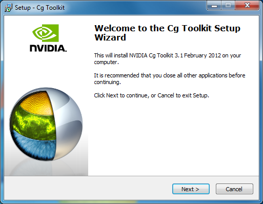
You will be presented with the Cg Toolkit Setup Wizard.
After carefully reading this nice welcome message, click “Next” to continue.
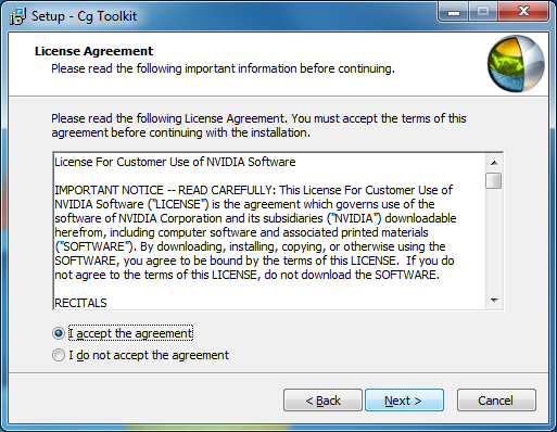
After reading the license agreement twice, select the “I accept the agreement” radio box and click “Next” to continue.
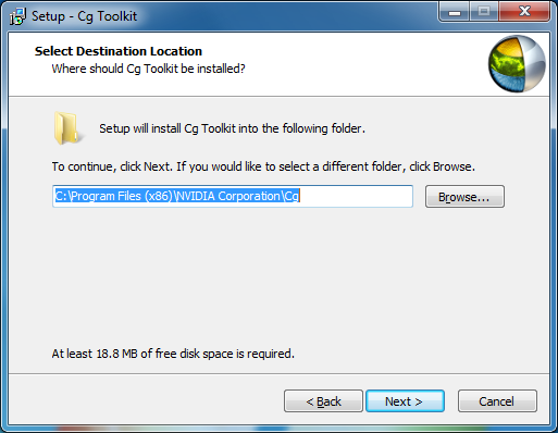
Choose your favorite installation folder and click “Next” to continue.
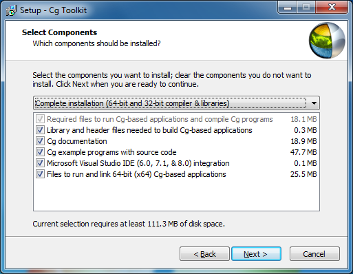
By default, the “Typical installation (32-bit compiler & libraries)” option is selected on the “Selected Components” page of the installation wizard. This may be fine if you never need to build your application to target 64-bit operating systems. Keep in mind that this choice should not be influenced by the fact that you may be running a 64-bit operating system at them moment. Your 64-bit operating system is perfectly capable of running 32-bit applications and your compiler (Visual Studio most likely if you are developing Windows applications) has no problems building 32-bit applications. If you are a perfectionist like myself, you will probably want to install everything anyways just in case you someday might maybe want to use it but never do. In that case, select the “Complete installation (64-bit & 32-bit compiler & libraries)“. Keep in mind that if you are targeting a 64-bit platform, then all of the 3rd party libraries you use in your application must also be built to target 64-bit platforms which is sometimes not always possible.
Choose the components to install and click “Next” to continue.
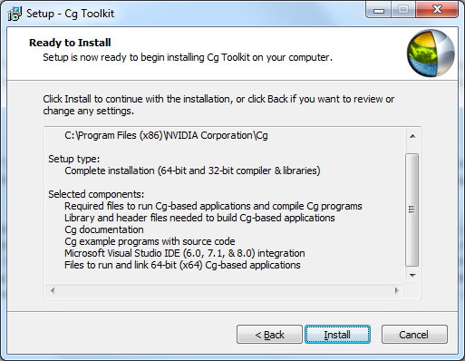
You will be presented with the “Ready to Install” page. Carefully confirm that all of the installation configurations are correct and if so, click the “Install” button.
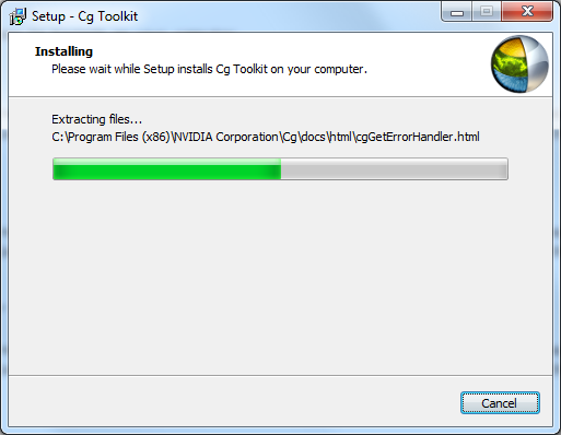
While it’s installing you can look at this next picture and you can get an idea of what the future holds:
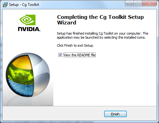
Make sure you have “View the README file” selected because I know how much everyone loves to view the README file after installing software. Click “Finish” to close the installation wizard dialog.
Creating an OpenGL Project
Now that we have the Cg toolkit installed, we can start creating our first Cg demo!
Open your favorite development IDE (for this tutorial, I will use Visual Studio 2010 but the steps shown here will be very similar to earlier versions of Visual Studio IDE).
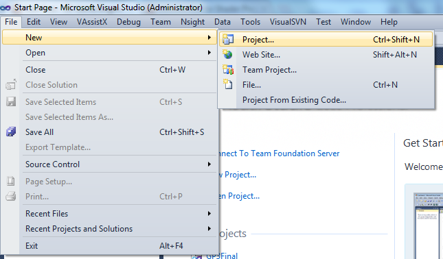
Create a new project by selecting “File -> New -> Project…” on the main menu.
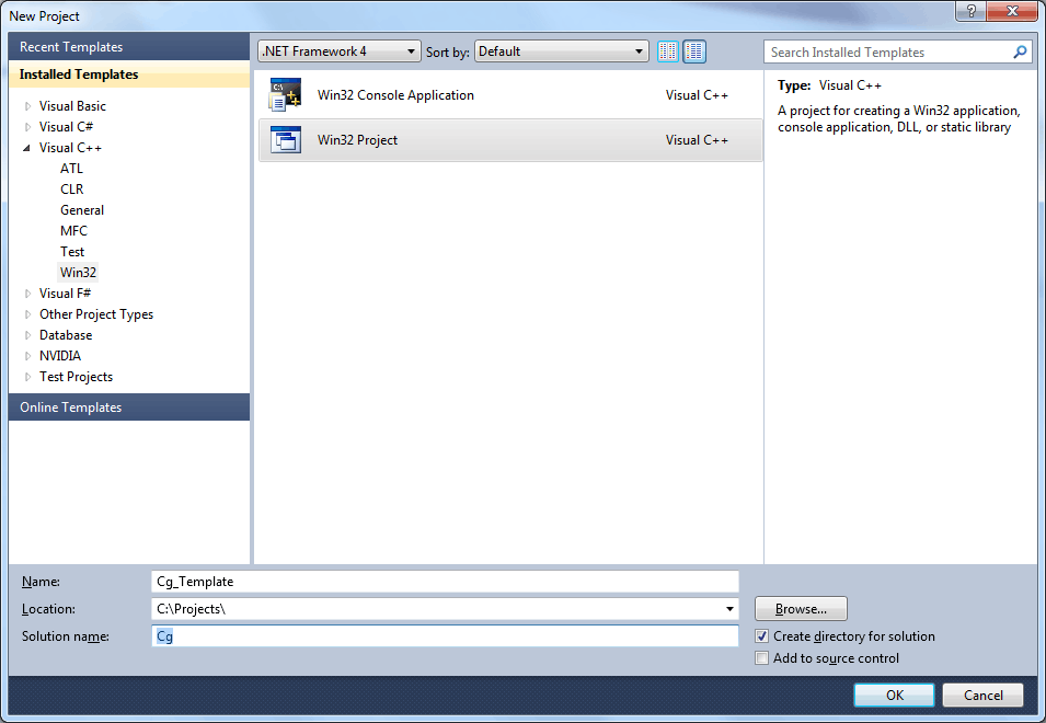
You will be presented with the “New Project” dialog box shown below.
In the “Templates” tree view on the left, select “Visual C++\Win32” and select the “Win32 Project” in the project templates frame.
Choose a nice name for your new project (I called mine “Cg_Template” but you are free to call yours whatever you want). Specify the base folder where you want the new project to be created and a name for your solution file (I called my “Cg” because I will probably be creating a few more “Cg” related projects in this solution later).
If all of your settings are correct, click the “OK” button to continue.
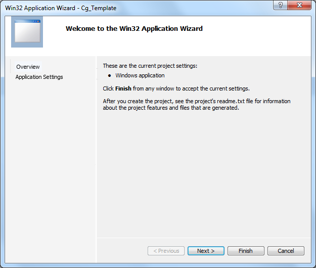
You will be presented with the “Win32 Application Wizard” dialog box. Click “Next” to continue.
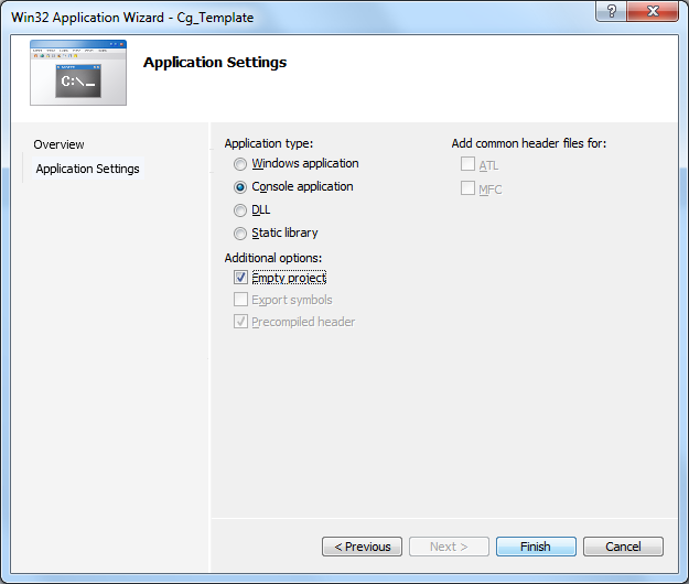
Select “Console application” under “Application type:” and check the “Empty project” check box. I prefer that Visual Studio doesn’t create any default files for me in my new project.
|
1 |
int main( int argc, char* argv[] ) |
|
1 |
int CALLBACK WinMain( HINSTANCE hInstance, HINSTANCE hPrevInstance, LPSTR lpCmdLine, int nCmdShow ) |
If you settings are correct, click the “Finish” button to continue.
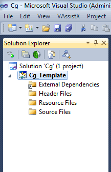
Visual Studio will create the new project and solution files and add them to the Solution Explorer.
Now our project is set up but before we start writing code, we should make sure the project is configured correctly with the dependencies described above.
Project Configuration
If we want to make our project can be compiled and run “out-of-the-box” and easy to maintain for future modifications, it’s a good idea to make sure that all of your project’s dependencies are located together with the project in the same directory, or in a directory that is accessible relative to your project’s root folder. This is especially true if you are working in a team with a source control system such as Subversion or Perforce. When a new member joins your programming team, you don’t want to fuss around with installing 3rd party libraries and making sure all of the environment variables are configured correctly so that all of the 3rd party include paths and library files can be found by your compiler. Instead, I suggest that you copy the 3rd party application extensions, libraries and header files to a directory that will be packaged together with your project’s source code and use path names that are relative to the location of your project files in the project settings and properties.
Pro-tip: Package all 3rd-party dependencies together with your source code.
Pro-tip: Do not specify 3rd-party include paths and library paths in Visual Studio’s default C++ project directories. Always explicitly provide paths to 3rd party libraries and headers relative to your project file.
I will follow my own advice here and copy the 3rd party dependencies into the directory that contains the solution file.
Copy 3rd Party Projects
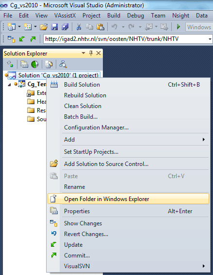
Open the folder that contains the solution file for your project. You can use the “Open Folder Location” short cut by right-clicking on the solution file in the solution explorer and selecting “Open Folder in Windows Explorer” option in the pop-up that appears.
In the directory where your solution file exists, create a directory called “external” or “3rdparty” or whatever your favorite directory naming convention is for storing 3rd party library and header files.
Inside the 3rd party directory you just created, create a folder called “Cg-3.1“.
Copy the “include“, “lib“, and “bin” folders from the root directory where you installed the Cg toolkit into the “Cg-3.1” directory you just created. You don’t need to copy the “docs” or the “examples” folders from the root directory of your Cg toolkit installation. The contents of these folders will not be used by our project.
The Cg toolkit provides a few additional headers and libraries that are not required by our project. In fact, if we leave them there they will most likely conflict with the header files that are defined in the freeglut library.
Open the “Cg-3.1\include\GL” folder and delete the “glut.h” header file. Also, open the “Cg-3.1\lib” folder and delete the glut32.lib library file. And finally, open the “Cg-3.1\bin” folder and delete the glut32.dll application extension file.
Also copy the other dependencies you will be using in this project:
- Copy the freeglut-2.8.0 directory to your externals directory.
- Copy the glew-1.7.0 directory to your externals directory.
- Copy the glm-0.9.3.2 directory to your externals directory.
Now that all of our 3rd party dependencies are in a folder relative to our solution file, we can configure our project settings so that the compiler knows where to find these files.
Create Main
If we created an empty project, then there will be no source files in the project. If this is the case, then all of the options that we need to configure in the project settings will not be available until we create at least 1 “.cpp” file.
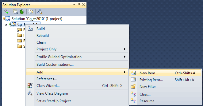
Right-click on the Cg_Template project in the project settings and choose “Add -> New Item…” from the pop-up menu that appears.
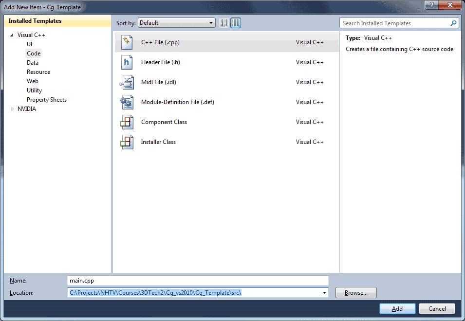
From the “Add New Item” dialog box that appears, select the “Visual C++\Code” templates in the tree view on the right and select the “C++ File (.cpp)” template type in the templates panel.
Give the new item a name (Like “main.cpp“) and add the new item to a sub-folder called “src” relative to the project folder.
Click the “Add” button to add the new item to your project.
We don’t need to add any code to this new file. It is sufficient that the file exists in our project to get Visual Studio to recognize our project as a C++ project and provide the additional “C/C++” options that we need to configure.
Configure “C/C++” Settings
Now we need to tell the Visual Studio compiler where to look for the 3rd-party header files.
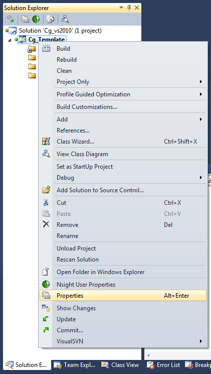
Right-click on the “Cg_Template” project node in the solution explorer and select “Properties” from the pop-up menu that appears.
The project Property Pages dialog will appear.
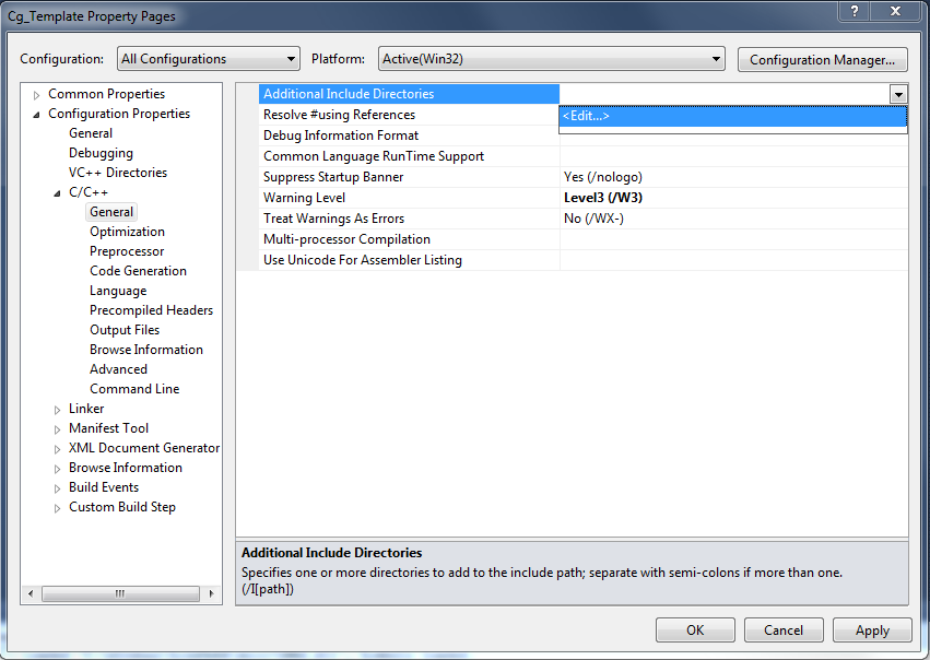
Since we want to apply these project settings to all configurations, select “All Configurations” from the “Configuration” drop-down menu.
In the tree view on the left, select “Configuration Properties \ C/C++ \ General” and click the “<Edit…>” option under “Additional Include Directories”
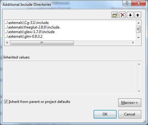
Add the paths to the include folders for the external dependencies we added earlier. Make sure your path names are always relative to the location of the project file. All directories and paths specified in the project settings are expressed relative to the project file. There is no need to include the “$(ProjectDir)” macro. Do not append the $(SolutionDir) macro to directories and paths in project settings because if your project is included in another solution located in another directory, your project settings will be broken!
You should add these paths to your “Additional Include Directories” property of your project settings.
- ..\externals\Cg-3.1\include
- ..\externals\freeglut-2.8.0\include
- ..\externals\glew-1.7.0\include
- ..\externals\glm-0.9.3.2
Press the “OK” button to close the dialog box and apply your changes to the project settings.
Configure Linker Options
We also need to tell Visual Studio where to find the 3rd-party library files that we need to link with our application.
If the Property Pages dialog box is not open, right-click on the “Cg_Template” project in the Solution Explorer and click the “Properties” option.
The Project Property dialog box should appear.
We will first tell Visual Studio which directories to search for library files.
Some of our dependencies have different library paths for Debug and Release builds. Let’s first configure the Debug library paths.
Make sure that “Debug” is selected in the “Configuration” drop-down menu.
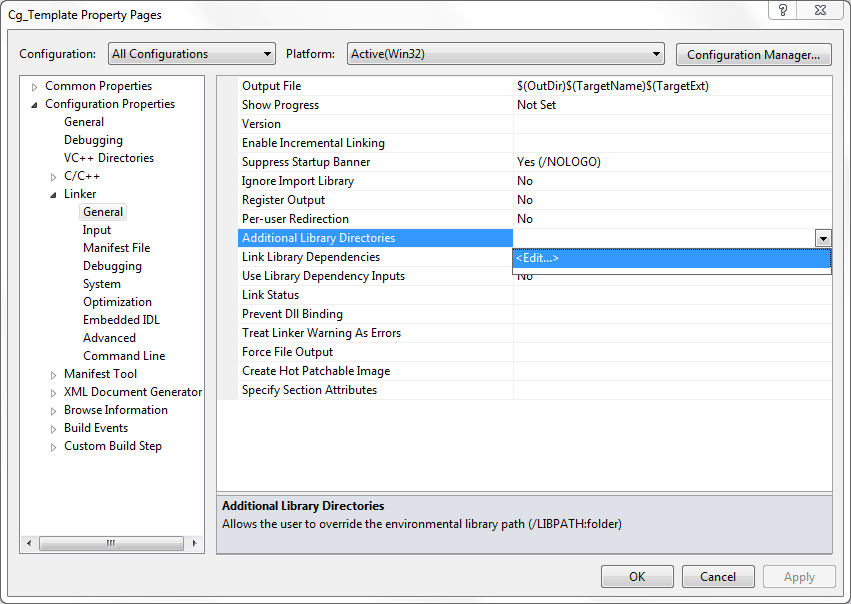
In the tree view on the left, select “Linker \ General” and choose “<Edit…> ” from the “Additional Library Directories” property.
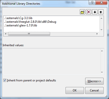
Add the following paths to the “Additional Library Directories” dialog that appears.
- ..\externals\Cg-3.1\lib
- ..\externals\freeglut-2.8.0\lib\x86\Debug
- ..\externals\glew-1.7.0\lib
As mentioned earlier, these paths should be expressed relative to the directory that contains the project file. By default, all paths in project properties are resolved relative to the current project’s directory.
Click “OK” to close the “Additional Library Directories” dialog box.
Now do the same for the “Release” configuration but using the following paths:
- ..\externals\Cg-3.1\lib
- ..\externals\freeglut-2.8.0\lib\x86
- ..\externals\glew-1.7.0\lib
Next, we want to tell Visual Studio which library files to link against.
This setting will apply to both “Debug” and “Release” builds so select “All Configurations” from the “Configuration” drop-down menu.
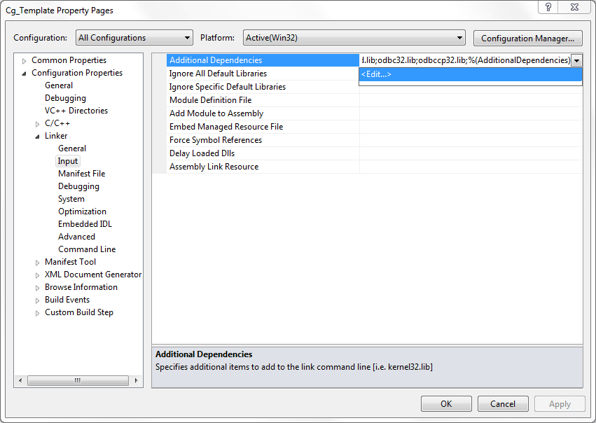
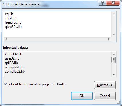
In the tree view on the left select “Linker / Input” and select “<Edit…>” from the “Additional Dependencies” property.
Adding the following library files:
- cg.lib
- cgGL.lib
- freeglut.lib
- glew32.lib
Each of these libraries has an accompanying DLL file that is implicitly loaded when the application starts. I will deal with the DLL files later when it’s time to run the demo.
Optionally, you can link against the static library versions for freeglut and glew. If you link against the static libraries then you don’t need to have the accompanying DLL present to run your program.
If you want to link against the static library versions then change:
- freeglut.lib to freeglut_static.lib
- glew32.lib to glew32s.lib
The Cg Toolkit does not provide static libraries so you cannot avoid requiring the DLL in this case.
Linking against static libraries as opposed to the dynamic library version has the advantage of requiring less files to package together with your application when you want to deploy it. I always prefer to link against static libraries if possible.
Close any dialog boxes that may be open by pressing the “OK” button to apply these configuration changes to your project.
With these configurations changes applied, we can finally start writing some code!
Creating the Cg Demo
Before we start writing any code, let’s think about what it is we want to accomplish. This demo is intended to show a very brief introduction to using Cg, so obviously we will need to initialize Cg in some way. We also want to render some geometry so we also need a way to define the geometry and render it using a simple Cg shader. Cg is platform agnostic which means that it is not generally concerned with which platform you are developing for. It should work if you are developing applications on Linux and the same shaders should work on Windows. Cg is also graphics API agnostic meaning that it will work with both OpenGL and DirectX. You only have to consider OpenGL applications generally use the right-handed coordinate system and DirectX applications generally uses the left-handed coordinate system. But with those considerations in mind, your shaders should work in both environments.
For this demo, I chose to implement my demo using OpenGL. So in this case I need a way to define the geometry and send it to the Cg shader using OpenGL.
If you are familiar with OpenGL, you may also be aware of the deprecation model that was introduced in OpenGL 3.0. A lot of the features and functionality that existed in OpenGL 2.0 and earlier were deprecated in OpenGL 3.0 and removed in OpenGL 3.1. In an effort to “keep up with technology” I don’t want to use any deprecated features of the OpenGL API. Writing my demo to be OpenGL 3.1 forward-compatible means that I can’t use any deprecated features of the OpenGL API such as fixed-function pipeline and the matrix stack. Using freeGLUT it’s easy to create an OpenGL 3.1 forward-compatable context in a platform-independent way.
Are there any further requirements? We need a way to view the geometry. Sending the geometry to the Cg shader is one thing, but positioning the object in the scene is also a valid requirement. For this demo, I’ve decided to apply a simple rotation to the object so we can view it from all sides. For simple rotation, I will apply a rotation matrix to the model before it is rendered.
Similar to the transformation being applied to the model, I also need a way to position the viewer somewhere in the scene. To determine the position of the viewer, I will use a view matrix. The GLM library provides a method to create a look-at view matrix based on the position of the camera (the eye position), and the thing you want to look at (the target position) so I’ll use that function to generate the view matrix.
Besides the model’s matrix which is used to position our model in the world and the view matrix which is used to position our viewer in the world, we also need to tell OpenGL something about the size and shape of our camera’s lens. To do this, we need to define a third matrix called the projection matrix which defines the zoom and aspect ratio of our resulting image. Again we’ll use a GLM function to create the projection matrix.
So let’s summarize our requirements:
- Define the geometry that we want to render.
- Use OpenGL to send the geometry to the Cg shader.
- Use a Cg shader to rasterize the image.
- Define a matrix transformation to position the model in the scene. (This is called the model matrix).
- Define a matrix transformation to position the viewer in the scene. (This is called the view matrix).
- Define a matrix transformation that determines the zoom and aspect ratio of our camera’s lense. (This is called the projection matrix).
Now we have a basic planning of how we are going to approach the problem, let’s see how we can do that.
Headers and Definitions
We must include a few headers that we will be using for the rest of the demo. I want to be clear that I try to write platform-independent code as much as possible, but sometimes there is a reason to include the windows header file. In this case, I want to be able to put debug output directly to the Visual Studio debug window. To do that, I need access to the OutputDebugString method which requires the windows header.
|
1 2 3 4 |
#ifdef _WIN32 #define WIN32_LEAN_AND_MEAN #include <windows.h> // For OutputDebugString #endif |
There are always a few headers that you will probably include in all of your projects. These headers usually come from the standard template library for reading and writing input from the console, the string template class, and a string builder class called “string stream”. Let’s include this here:
|
1 2 3 |
#include <iostream> #include <string> #include <sstream> |
We also need to include the header files for the dependencies we have (GLEW, GLUT, Cg, and GLM).
|
1 2 3 4 5 6 7 8 9 10 11 12 13 14 |
// NOTE: The GLEW header file must come before the GLUT header #define GLEW_STATIC // Link with static libs #include <GL/glew.h> #include <GL/wglew.h> // for WGL_EXT_swap_control #define FREEGLUT_STATIC // Link with static libs #include <GL/freeglut.h> // Cg #include <Cg/cgGL.h> // "Cg/cg.h" is implicitly included // Math library #include <glm/glm.hpp> #include <glm/gtc/matrix_transform.hpp> #include <glm/gtc/type_ptr.hpp> |
I’ll also define a few macros that will be used to convert an integer offset into a pointer type that is used by a few OpenGL functions.
|
1 2 |
#define MEMBER_OFFSET(s,m) ((char *)NULL + (offsetof(s,m))) #define BUFFER_OFFSET(i) ((char *)NULL + (i)) |
Similar to OpenGL, Cg requires you to create a “context” before you can use it. We must store a reference to the Cg context because we will need it when we load the effect files.
I also need to define variables to hold the references to the loaded effect, a technique within the effect, and a parameter in the effect. I’ll talk about effects, and techniques in more detail later.
|
1 2 3 4 5 6 7 8 9 10 |
// Cg variables // The context CGcontext g_cgContext = NULL; // Cg effect and pass variables. CGeffect g_cgEffect = NULL; CGtechnique g_cgTechnique = NULL; // Cg effect parameters // float4x4 modelViewProjection CGparameter g_cgModelViewProjection = NULL; |
And since the matrix stacks are deprecated in OpenGL 3.1, we need to define our own matrices for the model, view, and projection matrices. GLM provides the matrix template class to store our matrices.
|
1 2 3 4 5 6 |
// As of OpenGL 3.1 the matrix stack has been removed // from the specification. // We need to keep track of our own matrices now. glm::mat4 g_ProjectionMatrix; glm::mat4 g_ViewMatrix; glm::mat4 g_ModelMatrix; |
Cg Semantics
In Cg, you use “semantics” to map data coming from the application (the C++ part) into stream variables in the shader. You can think of a semantic as an association between the vertex information sent to the rendering pipeline in C++ and the vertex data in the shader. In OpenGL, this mapping is performed by telling OpenGL to apply an “attribute ID” to a named parameter in a shader using the glBindAttribLocation method. You then modify the value of the attribute using either the glVertexAttrib method, or specifying stream data (like a vertex stream) using glVertexAttribPointer method. Cg doesn’t require that you first bind the location of variable to an attribute ID, but instead it defines some default ID’s for different stream elements.
Cg defines the following default semantics and the default generic attribute ID’s that are bound to the semantic.
| Binding Semantics Name | Corresponding Data |
|---|---|
| POSITION, ATTR0 | Input Vertex, Generic Attribute 0 |
| BLENDWEIGHT, ATTR1 | Input vertex weight, Generic Attribute 1 |
| NORMAL, ATTR2 | Input normal, Generic Attribute 2 |
| DIFFUSE, COLOR0, ATTR3 | Input primary color, Generic Attribute 3 |
| SPECULAR, COLOR1, ATTR4 | Input secondary color, Generic Attribute 4 |
| TESSFACTOR, FOGCOORD, ATTR5 | Input fog coordinate, Generic Attribute 5 |
| PSIZE, ATTR6 | Input point size, Generic Attribute 6 |
| BLENDINDICES, ATTR7 | Generic Attribute 7 |
| TEXCOORD0-TEXCOORD7, ATTR8-ATTR15 | Input texture coordinates (texcoord0-texcoord7), Generic Attributes 8-15 |
| TANGENT, ATTR14 | Generic Attribute 14 |
| BINORMAL, ATTR15 | Generic Attribute 15 |
Don’t worry if this concept of semantics doesn’t make sense yet. I will go into more detail about semantics when I show how we send the vertex data to the shader program. I will just define a few macros that are used to refer to these predefined generic attributes.
|
1 2 3 4 |
// Define the default attribute ID's // for the POSITION and DIFFUSE Cg semantics. #define POSITION_ATTRIBUTE 0 #define DIFFUSE_ATTRIBUTE 3 |
In this case, the vertex position will be bound to the attribute ID 0 and the vertex color will be bound to the attribute ID 3.
Define the Geometry
For this demo, I will simply create a static array that defines the vertex data for our geometry. At a minimum, you must specify the position of each unique vertex and optionally, we can also define a color for each vertex.
We wan’t to define a structure that defines a single vertex of our geometry.
|
1 2 3 4 5 |
struct VertexXYZColor { glm::vec3 m_Pos; // X, Y, Z glm::vec3 m_Color; // R, G, B }; |
And a static vertex array to define the unique vertices of our geometry. In this case, I am defining a cube. We need to define the 8 unique vertex positions and the colors of each vertex.
|
1 2 3 4 5 6 7 8 9 10 11 |
// Define the 8 vertices of a unit cube VertexXYZColor g_Vertices[8] = { { glm::vec3( 1, 1, 1 ), glm::vec3( 1, 1, 1 ) }, // 0 { glm::vec3( -1, 1, 1 ), glm::vec3( 0, 1, 1 ) }, // 1 { glm::vec3( -1, -1, 1 ), glm::vec3( 0, 0, 1 ) }, // 2 { glm::vec3( 1, -1, 1 ), glm::vec3( 1, 0, 1 ) }, // 3 { glm::vec3( 1, -1, -1 ), glm::vec3( 1, 0, 0 ) }, // 4 { glm::vec3( -1, -1, -1 ), glm::vec3( 0, 0, 0 ) }, // 5 { glm::vec3( -1, 1, -1 ), glm::vec3( 0, 1, 0 ) }, // 6 { glm::vec3( 1, 1, -1 ), glm::vec3( 1, 1, 0 ) }, // 7 }; |
We also need to tell OpenGL the order when which the vertices should be sent to the vertex shader. To do that, we specify an index buffer that is used to define all of the triangles in our model.
|
1 2 3 4 5 6 7 8 9 10 |
// Define the vertex indices for the triangles // of the cube. GLuint g_Indices[36] = { 0, 1, 2, 2, 3, 0, // Front face 7, 4, 5, 5, 6, 7, // Back face 6, 5, 2, 2, 1, 6, // Left face 7, 0, 3, 3, 4, 7, // Right face 7, 6, 1, 1, 0, 7, // Top face 3, 2, 5, 5, 4, 3, // Bottom face }; |
If you’ve followed any of my previous OpenGL tutorials, then you have probably seen this model defined before. In previous tutorials I defined the cube model using quads which required 24 indices. Since OpenGL 3.0, the GL_QUAD primitive type has been deprecated and only point, line, and triangle primitives remain in the standard. To render the cube using triangles, I need to define 36 indices.
Back-Face Culling
As an optimization for very complex models, you may want to enable back-face culling which instructs OpenGL not to render triangles that are orientated away from the camera.
The direction a triangle is facing is determined by the order in which the triangles’s vertices are drawn. By default, triangles whose vertices are drawn in a counter-clockwise order are considered “front-facing” polygons and are passed on to the rasterization unit and polygons who’s vertices are drawn in a clock-wise order are considered “back-facing”. If back-face culling is enabled (with glEnable( GL_CULL_FACE )) then these polygons will not be passed to the rasterization unit.
With this in mind, we must take special care that the indices in the index buffer are specified in the correct order. Usually you won’t need to do this yourself. Most digital content creation software packages will take care of this detail for you but you should be aware of it in case you get a model from a modeling package that assumes that clock-wise facing polyons are “front-facing”. What you’ll see is a model that is viewable from the inside when you enable back-face culling.
Using VBO’s
Since we don’t want to use any deprecated features of OpenGL in this demo, we must load our geometry information into a vertex buffer. For a complete discussion of using vertex buffers in OpenGL, you can refer to my previous article titled Vertex Buffer Objects. For the remainder of this article, I will assume you know how to use VBO’s.
We will define a few variables that will be used to store the references to our VBO objects.
|
1 2 3 4 5 |
// OpenGL vertex buffers (VBO's) for our vertex data GLuint g_VertexBuffer = 0; GLuint g_IndexBuffer = 0; // OpenGL vertex array object (VAO) for our cube mesh. GLuint g_VertexArray = 0; |
Using VAO’s
The g_VertexArray parameter is used to define a vertex array object (VAO) that wraps up all of the different attribute arrays (vertex streams) that our geometry defines. In our case, we only define 2 attribute streams (the position and color of each vertex) but more complex models may have several attributes that they need to bind at once. Vertex Array Objects allow you to define multiple attribute streams in a single object. I will show you how to use them later when we initialize the cube geometry in OpenGL.
Checking for OpenGL Errors
OpenGL does not provide functionality to automatically call a function if an error occurs so we must manually check for any OpenGL errors everywhere we want to confirm if an OpenGL function call was used correctly. This is especially important if you want to check for proper use of the forward-compatible context in OpenGL 3.1 and higher.
|
1 2 3 4 5 6 7 8 9 10 11 12 13 14 15 16 17 18 19 20 |
inline void CheckOpenGLError( const char* msg, const char* file, int line ) { GLenum errorCode = GL_NO_ERROR; while ( ( errorCode = glGetError() ) != GL_NO_ERROR ) { std::stringstream ss; const GLubyte* errorString = gluErrorString(errorCode); if ( errorString != NULL ) { ss << file << "(" << line << "): OpenGL Error: " << errorString << ": " << msg << std::endl; #ifdef _WIN32 OutputDebugStringA( ss.str().c_str() ); #else std::cerr << ss; #endif } } } |
This error handler will output text to the Visual Studio debug output window. The output string is formatted in such a way that the user can double-click the line in the debug window and Visual Studio will show you the file, and the line of code that generated the error.
To make this easy to use, I will provide a macro that can be added to the end of OpenGL function invocations. But I don’t want to incur the overhead of error checking in Release builds so the macro will print the error in Debug builds but resolve to nothing in release builds.
|
1 2 3 4 5 |
#ifdef _DEBUG #define checkGL() CheckOpenGLError( __FUNCSIG__, __FILE__, __LINE__ ) #else #define checkGL() ((void*)0) // Do nothing in release builds. #endif |
Cg Error Handler
Cg on the other hand does allow you to register an error handler which is invoked whenever a Cg context error occurs.
The error handler must have the following signature:
|
1 2 3 |
typedef void (*CGerrorHandlerFunc)( CGcontext context, CGerror error, void * appdata ); |
This function has the following parameters:
- CGcontext context: The Cg context in which the error occurred or NULL if the context cannot be determined.
- CGerror error: An enumeration value that defines the error that occurred.
- void * appdata: The application data that was specified when the error handler was registered with cgSetErrorHandler.
Let’s first define the error handler that will later be registered with Cg.
|
1 2 3 4 5 6 7 8 9 10 11 12 13 14 15 16 17 18 19 20 21 22 23 24 25 |
// Error handler for Cg void CgErrorHandler( CGcontext context, CGerror error, void* appdata ) { if ( error != CG_NO_ERROR ) { std::stringstream ss; const char* pStr = cgGetErrorString(error); std::string strError = ( pStr == NULL ) ? "" : pStr; ss << "Cg ERROR: " << strError << std::endl; std::string strListing; if ( error == CG_COMPILER_ERROR ) { pStr = cgGetLastListing( context ); strListing = ( pStr == NULL ) ? "" : pStr; ss << strListing << std::endl; } #ifdef _WIN32 OutputDebugStringA( ss.str().c_str() ); #else std::cerr << ss; #endif } } |
This function uses the stringstream class to build an error message that we want to display to the user. The stringstream class is similar to an sprintf function in C, but you don’t have to use a format string to specify simple output.
On line 176, we check if the error that occurred was a script compilation error and if so, output the compiler error message that was generated. This error message is formatted in a way that allows the user to double-click the message in the output window and if the shader script file is added to the project (like a source file), then the file will be opened in the editor and the offending line will be selected.
We’ll register this function as the Cg error handler when we initialize the Cg context.
The Main Entry Point
Our main function will initialize all of the 3rd party libraries we are using and start the event processing loop.
|
1 2 3 4 5 6 7 8 9 10 11 12 |
int main( int argc, char* argv[] ) { InitGLUT( argc, argv ); InitGLEW(); InitGL(); InitCG(); // Start processing our event loop. glutMainLoop(); return 0; } |
You’ll notice that the first thing we do is initialize GLUT. GLUT is responsible for handling the main windows event loop. We can register callbacks to GLUT that allows us to handle keyboard presses (and releases in freeGLUT), detect mouse motion and mouse button clicking, and some joystick support. GLUT is also responsible for creating the OpenGL context and displaying our main rendering window. We must have an OpenGL context before we can do anything else (like checking for extensions with GLEW, and initializing Cg)
Initialize GLUT
With freeGLUT you can also specify the version of the OpenGL context that you want to use when a new window is created. For this demo, I wanted to use the OpenGL 3.1 version and not use any of the deprecated features of OpenGL 2.x. We can tell GLUT that we want a specific version as well as specify that the context should be forward-compatible. This means that it’s an error to use any deprecated functionality and the context doesn’t even have to implement the removed features. This may generate a lot of errors (especially if you use a 3rd party library that still uses a lot of deprecated features of OpenGL!) so using using a forward-compatible context may cause some things to stop working that otherwise used to work just fine without specifying a forward-compatible context.
By default, a backward-compatible context is always created unless otherwise specified. So generally, you don’t have to worry about accidently using deprecated features unless you know what you’re doing.
The fist thing I’ll do is initialize GLUT and create a window.
|
1 2 3 4 5 6 7 8 9 10 11 12 13 14 15 16 17 18 19 20 21 22 |
void InitGLUT( int argc, char* argv[] ) { glutInit( &argc, argv ); glutInitDisplayMode( GLUT_DOUBLE | GLUT_RGB | GLUT_DEPTH ); // Create an OpenGL 3.1 forward compatible context. // If you are targeting earlier hardware or you don't have an // OpenGL 3.1 compatible video card, simply remove the next two lines. glutInitContextVersion( 3, 1 ); // NOTE: Cg 3.1 does not support forward-compatible contexts! // glutInitContextFlags( GLUT_FORWARD_COMPATIBLE ); glutInitWindowSize( g_uiWindowWidth, g_uiWindowHeight ); int screenWidth = glutGet( GLUT_SCREEN_WIDTH ); int screenHeight = glutGet( GLUT_SCREEN_HEIGHT ); // Center the new window relative to the screen. glutInitWindowPosition( (screenWidth - g_uiWindowWidth)/2, (screenHeight - g_uiWindowHeight)/2 ); // Creating the window will also create the OpenGL context. glutCreateWindow( g_ApplicationName ); |
Before using GLUT, we must first call glutInit passing the command line arguments that were used to start the application.
The glutInitDisplayMode tells GLUT that we want an RGB frambuffer (GLUT_RBG), a depth buffer (GLUT_DEPTH), and enable double buffering (GLUT_DOUBLE) to reduce screen draw lag.
On line 214, we tell GLUT that we want to create an OpenGL 3.1 context and on line 216 (which is currently commented out) is where we would have told GLUT to create a forward-compatible context for us. The reason this line is commented out is because Cg requires the OpenGL context to be backward-compatible with earlier versions of OpenGL. Cg uses a lot of deprciated features of OpenGL so I suppose it’s easier to ignore forward-compatible contexts than remove all of the deprecated features from the Cg API.
The glutInitWindowSize tells GLUT how big we want the next window we create to be and the glutInitWindowPosition method will initialize the default position of the new window.
On line 227 the actual window is created. Doing this will also create the OpenGL context. With the context created, we can also initialize GLEW and Cg.
We must also register callback functions that will be invoked when something happens. GLUT provides a lot of slots for callbacks. Since I want to create a reusable template, I will register a lot of callbacks here even if I don’t actually use them. They may be useful in another demo.
|
1 2 3 4 5 6 7 8 9 10 11 12 13 14 15 16 17 |
// If the window is closed, return control to the main method. glutSetOption( GLUT_ACTION_ON_WINDOW_CLOSE, GLUT_ACTION_GLUTMAINLOOP_RETURNS ); // Register GLUT callbacks glutDisplayFunc(&OnDisplay); glutIdleFunc(&OnIdle); glutReshapeFunc(&OnReshape); glutKeyboardFunc(&OnKeyPressed); glutKeyboardUpFunc(&OnKeyReleased); glutSpecialFunc(&OnSpecialKeyPressed); glutSpecialUpFunc(&OnSpecialKeyReleased); glutMouseFunc(&OnMouseButton); glutMouseWheelFunc(&OnMouseWheel); glutMotionFunc(&OnMouseMotion); glutPassiveMotionFunc(&OnPassiveMouseMotion); glutCloseFunc(&OnClose); } |
On line 230, we specify that we want the GLUT event loop to return control to the main function when we close the Window. This is a feature that freeGLUT provides that wasn’t available in previous version of GLUT. The old GLUT library required you to exit the application using the exit() method.
On lines 233-244 the event callbacks are registered with GLUT. I won’t describe the functionality of each one here as I will handle that when we get to the function implementation.
Initialize GLEW
After we have created the OpenGL context, we can initialize GLEW. GLEW allows us to use all of the extensions and features that are provided by the 3.1 OpenGL context. GLEW will register all of the extensions that are available as well as provide the functionality to query the existence and support for extensions.
|
1 2 3 4 5 6 7 8 9 10 11 12 13 14 15 16 17 18 19 20 21 22 23 24 25 26 27 |
void InitGLEW() { glewExperimental = GL_TRUE; if ( glewInit() != GLEW_OK ) { std::cerr << "There was a problem initializing GLEW. Exiting..." << std::endl; exit(-1); } // Check for 3.1 support. // I've specified that a 3.1 forward-compatible context should be created. // so this parameter check should always pass if our context creation passed. // If we need access to deprecated features of OpenGL, we should check // the state of the GL_ARB_compatibility extension. if ( !GLEW_VERSION_3_1 ) { std::cerr << "OpenGL 3.1 required version support not present." << std::endl; exit(-1); } if ( WGLEW_EXT_swap_control ) { wglSwapIntervalEXT(0); // Disable vertical sync } checkGL(); } |
On line 251, I set the glewExperimental global variable to true. This will inform GLEW that we want to bind both the core and experimental features provided by the OpenGL implementation.
From the GLEW website (http://glew.sourceforge.net/basic.html):
GLEW obtains information on the supported extensions from the graphics driver. Experimental or pre-release drivers, however, might not report every available extension through the standard mechanism, in which case GLEW will report it unsupported. To circumvent this situation, the glewExperimental global switch can be turned on by setting it to GL_TRUE before calling glewInit(), which ensures that all extensions with valid entry points will be exposed.
If you have a problem with some of the extended functionality provided by GLEW, you may want to check that this flag is enabled.
GLEW is then initialized by calling glewInit.
For this demo, I only want to check to see if I have full OpenGL 3.1 core support. If so, I can use all of the functions and types that are defined in the OpenGL 3.1 core specification. If you don’t want to read through thousands of pages of OpenGL specification but you want to know what (non-depricated) functions are available, then you should refer to the OpenGL 3.3 Reference pages (http://www.opengl.org/sdk/docs/man3/. The OpenGL 3.3 Reference pages will be virtually identical to the functions and types described in the OpenGL 3.1 specification.
Also, if the WGL_EXT_swap_control extension is supported (this is a windows extension, so it may not be available on all platforms) then I want to disable V-sync by invoking wglSwapIntervalEXT(0). Doing this will allow my demo to run as fast as possible and not being bound to my screen’s refresh rate (which is 60 Hz in my case). You should be aware that if the frame-rate drops below your screen’s refresh rate, visible screen-tearing may occur.
Initialize OpenGL
We have already initialized the OpenGL context when we initialized GLUT but we also want to initialize a few default OpenGL states that will ensure the rendered model looks correct.
|
1 2 3 4 5 6 7 8 9 10 11 12 13 14 15 16 17 |
void InitGL() { // Clear any accumulated OpenGL errors. while ( glGetError() != GL_NO_ERROR ); // Output interesting information about the platform we are using std::cout << "Vendor: " << glGetString (GL_VENDOR) << std::endl; checkGL(); std::cout << "Renderer: " << glGetString (GL_RENDERER) << std::endl; checkGL(); std::cout << "Version: " << glGetString (GL_VERSION) << std::endl; checkGL(); std::cout << "GLSL: " << glGetString (GL_SHADING_LANGUAGE_VERSION) << std::endl; checkGL(); // Initialize some default OpenGL states glClearColor( 0.0f, 0.0f, 0.0f, 1 ); checkGL(); glClearDepth( 1.0 ); checkGL(); glEnable( GL_DEPTH_TEST ); checkGL(); glEnable( GL_CULL_FACE ); checkGL(); |
It can happen that other 3rd party libraries (like freeGLUT) can generate some OpenGL errors during their initialization phase. If this happens, we should clear the accumulated list of OpenGL errors before we start our own rendering code. To do that, we just call glGetError until the function returns GL_NO_ERROR.
On lines 283-286, we just print some interesting stuff about the rendering device that we’re using. This is useful if you want to detect why something might not be working. For this demo to work, this should output “3.1.0” for the “Version” info and “1.40” for the “GLSL” version.
The glClearColor specifies which color the background will be cleared to when we call glClear later and the glClearDepth method specifies the value to clear the depth buffer to.
By default, OpenGL does not have any states enabled (not even depth testing which is a pretty common feature). So at a minimum we must enable depth testing with glEnable( GL_DEPTH_TEST ). I also want to enable back-face culling so back-facing polygons are not rendered.
This is the basic OpenGL initialization. I also want to initialize my cube geometry in this function. I will assume the reader is familiar with OpenGL Vertex Buffer Objects (VBOs). If you are not familiar with VBO’s, then please refer to my previous article titled OpenGL Vertex Buffer Objects.
To “wrap” all of the attribute streams (in this case I only define position and color attribute streams) I will use a Vertex Array Object (VAO) (not to be confused with vertex arrays or vertex buffer objects). Vertex array objects are used to wrap vertex stream definitions. For example, if you want to tell OpenGL that the position vertex element is coming from a VBO with an offset of 0 and the normal vertex attribute is coming from the same VBO with another offset and the color vertex attribute is coming from a completely different VBO with an offset of 0 (it starts getting complicated when we start mixing interleaved and packed VBO’s). Instead of binding and enabling all of the different attribute streams, we can use a Vertex Array Object to combine all of the different streams into a single binding. For this, we will use Vertex Array Objects.
|
1 2 3 4 5 6 7 8 9 10 11 12 13 14 15 16 17 18 19 20 21 22 23 24 25 26 27 28 |
// Create the VAO glGenVertexArrays( 1, &g_VertexArray ); checkGL(); glBindVertexArray( g_VertexArray ); checkGL(); // Create our VBO's glGenBuffers(1, &g_VertexBuffer ); checkGL(); glGenBuffers(1, &g_IndexBuffer ); checkGL(); // Copy the vertex data to the buffers glBindBuffer( GL_ARRAY_BUFFER, g_VertexBuffer ); checkGL(); glBufferData( GL_ARRAY_BUFFER, sizeof(g_Vertices), g_Vertices, GL_STATIC_DRAW ); checkGL(); // Bind data to the attribute streams glVertexAttribPointer(POSITION_ATTRIBUTE, 3, GL_FLOAT, GL_FALSE, sizeof(VertexXYZColor), MEMBER_OFFSET(VertexXYZColor,m_Pos) ); checkGL(); glEnableVertexAttribArray(POSITION_ATTRIBUTE); checkGL(); glVertexAttribPointer(DIFFUSE_ATTRIBUTE, 3, GL_FLOAT, GL_FALSE, sizeof(VertexXYZColor), MEMBER_OFFSET(VertexXYZColor,m_Color) ); checkGL(); glEnableVertexAttribArray(DIFFUSE_ATTRIBUTE); checkGL(); // Unbind the vertex array object. glBindVertexArray(0); checkGL(); // Unbind the vertex buffer glBindBuffer( GL_ARRAY_BUFFER, 0 ); checkGL(); // Copy the index data to the buffers glBindBuffer( GL_ELEMENT_ARRAY_BUFFER, g_IndexBuffer ); checkGL(); glBufferData( GL_ELEMENT_ARRAY_BUFFER, sizeof(g_Indices), g_Indices, GL_STATIC_DRAW ); checkGL(); glBindBuffer( GL_ELEMENT_ARRAY_BUFFER, 0 ); checkGL(); |
Similar to VBO’s, we must first generate a Vertex Array Object ID using the glGenVertexArrays. In order to capture the generic vertex attribute data to the VAO, we must also bind it using glBindVertexArray.
On line 300, unique VBO ID’s are generated for the vertex buffer and the index buffer. The vertex data is copied to the VBO using the glBufferData command.
On line 308, we bind the position data from the VBO to the generic vertex attribute defined by the POSITION_ATTRIBUTE macro (which should be 0).
We must also enable the position stream when we render the geometry. To do that, we use the glEnableVertexAttribArray. This is equivalent to the glEnableClientState function from the OpenGL 2.x specification but as of OpenGL 3.0, client stat data has been deprecated and removed in OpenGL 3.1.
We also need to bind the vertex color stream to the DIFFUSE_ATTRIBUTE generic attribute (the attribute ID for the color data is 3). And the attribute stream is enabled with glEnableVertexAttribArray.
At this point, all of the vertex attribute data has been capture to the VAO so we can unbind the VAO object by binding to the “invalid” vertex array object 0.
On line 317, we must also unbind the VBO.
Since the index buffer data does not define stream data, we cannot bind it to the VAO. Instead, we must fill the VBO that defines the index buffer and bind it manually in the render method which I will show later.
And finally, I also want to create a view matrix that can be used to position the viewer in the scene.
|
1 2 3 |
// Initial view matrix g_ViewMatrix = glm::lookAt( g_CameraPosition, glm::vec3(0,0,0), glm::vec3(0,1,0) ); } |
We’ll use the glm::lookAt method to generate an appropriate view matrix that can be applied to the geometry in the vertex program.
Initialize Cg
The last subsystem that we must initialize is Cg. In summary, we must create a Cg context, initialize the context state, load an effect file, get a valid technique from the effect, and retrieve any shader parameters that we need to modify.
First, let’s create a Cg context.
|
1 2 3 4 5 6 7 8 9 10 11 12 13 |
void InitCG() { // Register the error handler cgSetErrorHandler( &CgErrorHandler, NULL ); // Create the Cg context. g_cgContext = cgCreateContext(); // Register the default state assignments for OpenGL. // See the section titled "OpenGL State" in the CgUserManual. cgGLRegisterStates( g_cgContext ); // This will allow the Cg runtime to manage texture binding. cgGLSetManageTextureParameters( g_cgContext, CG_TRUE ); |
We first register the Cg error handler. I’ll use the CgErrorHandler method that I defined earlier to capture and output any errors to the debug console. If you want to catch compiler errors while your writing Cg shaders, you should have an error handler registered. Otherwise it’s going to be very difficult to figure out why your shader isn’t working.
On line 334, the Cg context is created and stored in the global variable.
Since we are using OpenGL, we must tell Cg to create a bunch of OpenGL state assignments. OpenGL state assignments allow the shader programmer to enable or disable OpenGL states, set state values such as the winding order of front-facing polygons, polygon rasterization modes, polygon offsets, shader program bindings, or a plethora of other OpenGL states directly in the shader script. I will not go into great detail about the state assignments in CgFX. For now, just make sure you tell the Cg context to register the state assignments by calling cgGLRegisterStates otherwise your shaders won’t work.
Optionally, we can also tell Cg to automatically bind OpenGL textures that have been assigned to sampler parameters in the effect file. To do this we call cgGLSetManageTextureParameters with the current context setting it to CG_TRUE.
The next thing we are going to do is load the effect file and retrieve a parameter that has been defined in the shader. Don’t worry too much about the contents of the shader file for now. I will show the vertex program and the fragment program later in the article.
|
1 2 3 4 5 6 7 8 9 10 11 12 13 14 15 16 17 18 19 20 21 22 23 |
// Load the CGfx file g_cgEffect = cgCreateEffectFromFile( g_cgContext, g_ShaderProgramName, NULL ); if ( g_cgEffect == NULL ) exit(-1); // Validate the technique g_cgTechnique = cgGetFirstTechnique( g_cgEffect ); while ( g_cgTechnique != NULL && cgValidateTechnique(g_cgTechnique) == CG_FALSE ) { std::cerr << "Cg ERROR: Technique with name " << cgGetTechniqueName(g_cgTechnique) << " did not pass validation." << std::endl; g_cgTechnique = cgGetNextTechnique(g_cgTechnique); } // Make sure we found a valid technique if ( g_cgTechnique == NULL || cgIsTechniqueValidated(g_cgTechnique) == CG_FALSE ) { std::cerr << "Cg ERROR: Could not find any valid techniques." << std::endl; exit(-1); } // Get the effect parameters g_cgModelViewProjection = cgGetNamedEffectParameter(g_cgEffect, "ModelViewProjection" ); } |
On line 343, we use the cgCreateEffectFromFile whose arguments are a valid Cg context and a null-terminated string that represents the path to the shader effect file to load.
You can load Cg effect files in two ways. You can load the individual shader programs (vertex program, fragment program, or geometry program) and then link these shaders into a single shader program for use by the programmable shader pipeline (this is similar to how GLSL shader programs are loaded), or you can load a single file called an effect file (usually this file has the .cgfx extension) and this single file can contain the entry points for the vertex, fragment, and geometry programs in one. The CgFX files can be loaded, compiled and linked in a single step using the cgCreateEffectFromFile method. I will use this method for all of my samples because it easier than loading individual shader programs.
If the effect file loaded correctly, we get the first technique that exists in the effect file using the cgGetFirstTechnique method. A technique describes how a particular effect is implemented. An effect file can contain several techniques. You can have a set of OpenGL techniques and a set of DirectX techniques in the same effect file. You can also create a technique for “high-quality” shader effects, “medium quality” shader effects, and “low-quality” shader effects. You may want to create one technique that does Lambert (diffuse only) shading and another technique that performs Phong (diffuse and specular) in a single file.
Generally, the shader programmer will define several versions of the same effect in the effect file. The highest quality effect will be defined in the first technique, but if the end-user has a lower-end graphics card, that technique may not be validated. In this case, the next technique present in the effect file will define the “medium-quality” effect which may use an older profile. If that technique still doesn’t pass, then the “low-quality” technique will be defined last which uses an even older profile version. Using this method, the application can query the first technique and if it validates, use it, but if it doesn’t, try the next-lowest quality technique until you either run out of techniques, or you find one that validates on the user’s hardware. This is the method I use to find a valid technique. I will show how to define a technique later when I talk about the CgFX file.
If we found a valid technique, then we query the effect for a parameter defined in the file. In this case, I only define a single parameter that is used to store the model-view-projection matrix. A reference to the effect parameter is stored in a global variable which I will use later to set the value of the parameter before we render the geometry.
Idle Function
Whenever GLUT determines there is no events to process, there may be some idle time. If that happens, then we can perform our program’s game logic. In this case, I simply perform a rotation operation on the geometry.
|
1 2 3 4 5 6 7 8 9 10 11 12 13 14 15 16 |
void OnIdle() { static ElapsedTime elapsedTime; const float fRotationRate = 0.05f; // Rotations per second. float fDeltaTime = elapsedTime.GetElapsedTime(); if ( m_bEnableAnimation ) // Rotate the object. { g_ModelMatrix = glm::rotate( g_ModelMatrix, ( fRotationRate * 360.0f ) * fDeltaTime, glm::vec3(1,0,0) ); g_ModelMatrix = glm::rotate( g_ModelMatrix, ( fRotationRate * 360.0f ) * fDeltaTime, glm::vec3(0,1,0) ); g_ModelMatrix = glm::rotate( g_ModelMatrix, ( fRotationRate * 360.0f ) * fDeltaTime, glm::vec3(0,0,1) ); } glutPostRedisplay(); } |
This method will simply rotate the model matrix around the X, Y, and Z axis.
If the game state (in this case the model matrix) changes, then we want to tell GLUT that we want to redraw our scene. To do that we call glutPostRedisplay.
Window Resizing
When the render window changes shape (width or height) then we need to update OpenGL’s viewport and we need to rebuild the projection matrix to account for the change in aspect ratio (screen width / screen height).
|
1 2 3 4 5 6 7 8 9 |
void OnReshape( int width, int height ) { if ( height < 1 ) height = 1; // Full-screen view port glViewport( 0, 0, width, height ); checkGL(); g_ProjectionMatrix = glm::perspective( 45.0f, width/(float)height, 0.1f, 1000.0f ); } |
On line 413, we update the OpenGL viewport using the glViewport method. We also have to recompute the projection matrix. Since the OpenGL matrix stack is removed in OpenGL 3.1, we have to keep track of our own matrices. GLM provides a method to define a perspective projection matrix in a similar way that gluPerspective does.
The Display Method
The OnDisplay function will send the geometry to OpenGL and we will use the Cg effect we loaded earlier to perform the vertex transformation and fragment coloring.
|
1 2 3 4 5 6 7 8 9 10 11 12 13 14 15 16 17 18 19 20 21 22 23 24 25 26 |
void OnDisplay() { glClear( GL_COLOR_BUFFER_BIT | GL_DEPTH_BUFFER_BIT ); checkGL(); glBindVertexArray(g_VertexArray); checkGL(); glBindBuffer( GL_ELEMENT_ARRAY_BUFFER, g_IndexBuffer ); checkGL(); glm::mat4 modelViewProjectionMatrix = g_ProjectionMatrix * g_ViewMatrix * g_ModelMatrix; cgSetParameterValuefc( g_cgModelViewProjection, 16, glm::value_ptr(modelViewProjectionMatrix) ); CGpass pass = cgGetFirstPass(g_cgTechnique); while ( pass ) { cgSetPassState(pass); glDrawElements( GL_TRIANGLES, sizeof(g_Indices)/sizeof(GLuint), GL_UNSIGNED_INT, BUFFER_OFFSET(0) ); checkGL(); cgResetPassState(pass); pass = cgGetNextPass(pass); } // Unbind! glBindVertexArray(0); checkGL(); glBindBuffer( GL_ELEMENT_ARRAY_BUFFER, 0 ); checkGL(); glutSwapBuffers(); } |
The first thing we do is clear the color buffer and the depth buffer using glClear.
On line 422, the Vertex Array Object (VAO) we defined earlier is bound. Without the VAO, we would have to bind all of the generic vertex attributes individually that our geometry requires to render (in this case, only the position and color vertex attributes). With complex geometry this may impose some unwanted overhead. With VAO’s we can bind all of our attributes with a single method invocation.
The index buffer still needs to be bound separately because it does not define vertex attributes but rather just the order in which vertices must be sent to the rendering pipeline.
The model-view-projection matrix is computed by multiplying the three matrices together. It’s easy to remember the order to perform the multiplication if you remember that OpenGL uses a right-handed coordinate system. Then you just have to remember that since it’s a right-handed coordinate system, the transformations are read right-to-left. In this case, if we read right-to-left, we have:
- Take the model matrix,
- Multiply the model matrix by the view matrix (this gives the model-view matrix),
- Multiply the model-view matrix by the projection matrix (this gives the model-view-projection matrix)
When we look at the vertex program, we’ll see this again when we transform the vertex from model-space into clip-space.
On line 426, the ModelViewProjection Cg parameter is updated with the pre-computed model-view-projection matrix.
To render a multi-pass effect, we need to loop through all of the passes defined in a particular effect. We retrieve the first pass defined in the effect and we render the geometry once for each pass. I will talk about passes in more detail later when I discuss the effect file.
The cgSetPassState method will actually bind our vertex and fragment shader programs to the rendering pipeline. This is required if we want to OpenGL to use our custom shader instead of rendering with the fixed-function pipeline.
The cgResetPassState will unbind the custom shader programs and reset the OpenGL rendering pipeline back to fixed-function.
After we render the geometry, we should not forget to unbind the VAO and the index buffer VBO.
To tell GLUT to display the frame, we call the glutSwapBuffers method. This will instruct GLUT to swap the front and back buffers so we can see the scene we just rendered.
Terminate and Cleanup
We should not forget to cleanup any parameters and data that we have allocated.
|
1 2 3 4 5 6 7 8 9 10 11 12 13 14 15 16 17 18 19 20 21 22 23 24 25 26 27 28 29 30 31 32 33 34 |
void OnClose() { // Delete the buffers we allocated if ( g_VertexBuffer != 0 ) { glDeleteBuffers( 1, &g_VertexBuffer ); checkGL(); g_VertexBuffer = 0; } if ( g_IndexBuffer != 0 ) { glDeleteBuffers( 1, &g_IndexBuffer ); checkGL(); g_IndexBuffer = 0; } if ( g_VertexArray != 0 ) { glDeleteVertexArrays(1, &g_VertexArray ); checkGL(); g_VertexArray = 0; } if ( g_cgEffect != NULL ) { cgDestroyEffect(g_cgEffect); g_cgEffect = NULL; } if ( g_cgContext != NULL ) { cgDestroyContext( g_cgContext ); g_cgContext = NULL; } cgSetErrorHandler( NULL, NULL ); } |
You may argue that we don’t need to destroy the Cg effect here if we are just going to destroy the Cg context anyways. This may be true, but I’m a perfectionist so I have to be thorough.
The CgFX Effect File
Now I will show you the different parts of the CgFX file. This is an extremly simple effect file and contains (almost) the minimum amount of code that is required to define a valid effect. I will first look at the vertex program, then I will show the fragment program and I will also show how we define the the technique for our simple effect.
Definitions and Global Parameters
First we’ll define a few structures whose only purpose is to group the parameters that are passed from the application as well as the parameters that we pass from the vertex program to the fragment program.
|
1 2 3 4 5 |
struct AppData { in float3 Position : POSITION; in float3 Color : COLOR; }; |
The AppData structure defines the vertex attributes that are being passed from the application to the vertex program. This structure definition looks very similar to a structure definition in the C programming language. In fact, Cg is a super-set of the C programming language. What may seem unfamiliar to the reader is the semantic syntax. In this case, there are two parameters defined in the struct. Each parameter is bound to application data by it’s semantic. In this case, the POSITION semantic binds the Position parameter to the generic vertex attribute with ID 0 and the COLOR semantic binds the Color parameter to the generic vertex attribute with ID 3. We can also define more parameters in this structure, but we should take care that the correct vertex attribute is bound to the correct attribute ID (for example, the NORMAL vertex attribute must be bound to the generic vertex attribute with ID 2).
Next, we’ll define a structure for passing information from the vertex shader to the fragment shader.
|
1 2 3 4 5 |
struct v2f { float4 Position : POSITION; float4 Color : COLOR; }; |
This struct defines the same parameters with the same names and the same semantics as the AppData structure. The only difference is the type of the parameters. The application sends 3-component floating-point values and this struct passes 4-component floating-point values.
Besides the types of the parameters, there is something different about the position parameter in this struct compared to the AppData structure defined earlier. The Position parameter in this struct defines the position of the vertex in clip-space whereas the Position parameter that is passed from the application is always in model-space (or local-space). We will see how to convert the model-space vertex to clip-space when we look at the vertex parameter.
These two structures that are defined (AppData and v2f) define varying data. Varying data is different for each invocation of the vertex program. You can also define uniform data in the shader program. Uniform parameters remain constant for a single pass of the shader program through the different stages of the rendering pipeline. If you were to think of the shader program as a for-loop in the C programming language, then the varying data would be the loop-index variable or any variable which changes each time the inner loop is executed and the uniform variable would be a constant (read-only) variable that is initialized before execution of the for-loop.
Next I will define the uniform variable which is initialized by the application before the shader program is executed. The only uniform parameter I declare is the one that stores the value of the ModelViewProjection matrix. Since it only needs to be calculated once to render a model, it makes sense to pre-compute the combined model-view-projection matrix in the application and send the value to the shader program using a uniform variable.
|
1 |
float4x4 ModelViewProjection; |
The ModelViewProjection variable is a 4×4 homogeneous matrix that is used to transform the vertex position attribute from model-space to clip-space in a single matrix multiplication.
Global parameters defined in this way can be either used directly in the vertex program, fragment program or any function defined in the effect file (just like a global parameter defined in a C file) or it can be used as a parameter to the entry-point for the vertex program, fragment program, or both. In this sample, I will use the ModelViewProjection global variable as a uniform parameter to the vertex program.
The Vertex Program
The vertex program is responsible for receiving the vertex attribute data from the application and at a very minimum, it must return the vertex position in clip-space. The vertex program may perform any number of additional actions but it must at least compute and return the vertex position in clip-space. In this example, the simple vertex program will also pass-through the vertex color attribute to the fragment program.
|
1 2 3 4 5 6 7 8 9 10 |
v2f mainVP( AppData IN, uniform float4x4 modelViewProjection ) { v2f OUT; OUT.Position = mul( modelViewProjection, float4(IN.Position, 1) ); OUT.Color = float4( IN.Color, 1.0 ); return OUT; } |
The mainVP function is the entry-point for the vertex program. It takes the varying parameters defined in the AppData struct as well as the uniform mode-view-projection matrix as parameters to the function.
As mentioned earlier, at a minimum the vertex program must compute the vertex position in clip-space. This is done by multiplying the vertex position in model-space by the model-view-projection matrix parameter. Again, we follow the right-to-left matrix multiplication (because we accept that OpenGL is using a right-handed coordinate system and matrices are stored in column-major order).
|
1 |
OUT.Position = mul( modelViewProjection, <strong>float4(IN.Position, 1)</strong> ); |
to
|
1 |
OUT.Position = mul( <strong>float4(IN.Position, 1)</strong>, modelViewProjection ); |
The 3-component color value is converted to a 4-component value to be passed to the fragment program.
The Fragment Program
This fragment program is probably the most simple fragment program I could imagine. It simply returns the color value that was passed to it from the vertex program.
|
1 2 3 4 |
float4 mainFP( v2f IN ) : COLOR { return IN.Color; } |
The mainFP function is the entry-point for the fragment program. It accepts at it’s only argument a parameter of type v2f. Although this structure defines both a position and a color value, only the color value is valid in this fragment program. This is because the position parameter is only used as the output of the vertex program and is not used by the fragment program.
Techniques and Passes
Each CgFX file describes a particular effect (such as lambert, phong, multi-texture blending, or bump-mapping lighting effect). How the effect is achieved may be different depending on the available hardware and graphics API’s. Techniques are used to target different levels of GPU functionality. Certain effects may not be supported on older hardware so we can define a technique that supports newer hardware and another fall-back technique that has support for older hardware. We can also define techniques that define different levels-of-detail (LOD) where the first technique in the effect file defines the “near” detail effect and another technique that describes the “far” effect and the application can switch between these techniques based on the distance the object is away from the camera.
At least one technique must exist in the CgFX file. For this sample, I will only define a single technique that is used to render this simple effect.
|
1 2 3 4 |
technique t0 { ... } |
As you can see here, there isn’t much to defining a technique. Only the keyword ‘technique‘ must appear followed by a unique name to identify the technique. In this case, the techniques name is “t0“. What makes the technique interesting is the contents that appear between the curly-braces.
A technique must consist of one or more passes that describe how the technique performs it’s work.
Each pass in a technique describes the vertex program, the fragment program, the geometry program, tessellation control program, or tessellation evaluation program that is used to render the effect. Each statement that appears in a pass block corresponds to a CgFX state assignment. The state assignment will make modifications to the OpenGL state machine and therefor allowing the custom shader programs to function for the specific pass.
For this sample, I only define a single pass which will define a vertex program and a fragment program that are bound to the rendering pipeline when the passes state is set with cgSetPassState.
|
1 2 3 4 5 6 7 8 |
technique t0 { pass p0 { VertexProgram = compile gp4vp mainVP( ModelViewProjection ); FragmentProgram = compile gp4fp mainFP(); } } |
This may solve issues with ATI hardware but I’m not sure because I don’t have access to ATI hardware.
Please let me know if you have problems with these profiles on ATI hardware by posting a comment at the end of this post.
In this case, I want to specify the vertex program and the fragment program that should be used when rendering this effect.
The VertexProgram and FragmentProgram state assignments have the following syntax:
|
1 2 |
VertexProgram = compile profile "-po profileOptions" main(args); FragmentProgram = compile profile "-po profileOptions" main(args); |
Where
- compile: Is a keyword that must appear in the statement. It specifies that the shader program is to be compiled using a particular profile.
- profile: Specifies the shader profile that is used to compile this shader program. The gp4vp and gp4fp profiles shown in this example refer to the OpenGL 3.x API (which is what I’m using in this sample). If you are using an ATI graphics adapter and you are having problems with these profiles, you may want to replace gp4vp with glslv and gp4fp with glslf.
- -po profileOptions: You can specify a list of profile options to the Cg compiler. Profile options are specific to the chosen profile. For a list of the profile options, you can refer to chapter 3 of the Cg 3.1 Reference Manual available here: http://developer.download.nvidia.com/cg/Cg_3.1/Cg-3.1_April2012_ReferenceManual.pdf.
- main(args): This is the name of the entry point for your shader programs. You may also specify arguments to the function.
In this example, I only specify a single argument to the vertex program. The argument is the global variable ModelViewProjection that was defined previously in the CgFX source file.
The Final Result
If everything works correctly, you should see something similar to what is shown below.
Simple Shader Demo
Exercise
- Download the source file from Cg Template – Exercise.zip.
- Open the project file in Visual Studio
- Fix the program so that it uses Cg to render the cube in the center of the scene instead of using the fixed-function pipeline.
Reference
| Cg 3.1 Reference Manual: Release 3.1 – NVIDIA Corporation. May 1, 2012 |
Download the Source
The source code for this demo is available upon request.



Hello, I really like the way, you post Articles. You don’t post a lot of them, but these articles get really detailed.
Keep it up, and remember, you have readers 🙂
Thanks Matheusdev.
I prefer quality over quantity. But I wish I could just write posts all day, but I also have to schedule time for other parts of my job and my family too 😉